I received these pics last week already, but I haven't found the time to upload them now.
These reflect all the changes that have been discussed and made.
As they probably look mostly the same than before for most of you, I'll try to explain what has changed here.
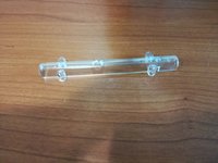
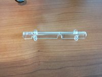
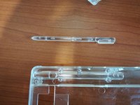
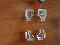
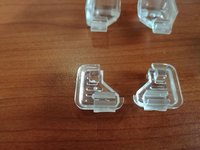
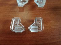
Here you can the changed Stylus holder. What has changed here is that small cut (you can see it clearly on the left side on the third picture.
This has been changed because it was almost impossible to remove the stylus otherwise.
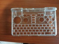
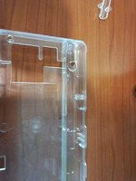
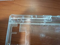
This was the biggest change: The moulds weren't properly aligned, so ALL holes were a bit off. The have no been moved to the middle!
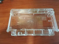
The plastic inside the battery compartment has been thickened a bit, as it couldn't be properly filled with the mold before.
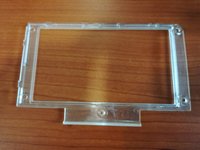
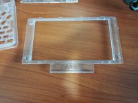
The opening of the frame has been changed a tiny bit, as the LCD wasn't properly aligned in the middle.
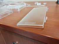
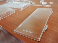
The clips have been strengthened a bit.
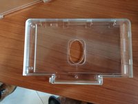
The height of the bridges has been changed a bit so that it closes properly.
Sholderbuttons have been fixed to properly work (hopefully!)
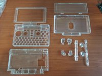
Just showing the full set

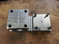
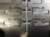
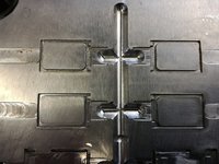
These are the moulds for the speaker sealing.
They are made of silicone and the parts will be produced on Monday, which is why we only see pictures of the moulds with the changes applied.
These have been changed to properly fit on top of the speakers.
Well, so much for the current state of the cases.
One more information about the whining noise the Pyra does (I've already posted about this in the other thread, so most of you will already know):
As it looks like, we don't need to use Tantalum capacitors.
Nikolaus found a different solution by replacing somr parts.
Here is his detailed explanation (from the other track):
So basically, the tps2505 (the "wonky chip") drives the capacitors with an audible frequency - which is causing the noise. By replacing it with different ones, we can change the frequency into a non-audible one.
The only thing we need to check is that the new circuit can provide enough power for the USB port.
Fortunately, that can be tested with a simple PCB.
This has already been designed, layouted and is in production. The parts also have been ordered.
While waiting for it to arrive, Nikolaus will change the layout on the mainboard already, so that we can put it into production right away as soon as we confirm it to be working.
So yep, the next prototypes will already have that new circuit included (if it works, but we're 99,9% sure it will).
So much for today. Not too many news, but a few nice pictures
These reflect all the changes that have been discussed and made.
As they probably look mostly the same than before for most of you, I'll try to explain what has changed here.


Here you can the changed Stylus holder. What has changed here is that small cut (you can see it clearly on the left side on the third picture.
This has been changed because it was almost impossible to remove the stylus otherwise.

This was the biggest change: The moulds weren't properly aligned, so ALL holes were a bit off. The have no been moved to the middle!

The plastic inside the battery compartment has been thickened a bit, as it couldn't be properly filled with the mold before.


The opening of the frame has been changed a tiny bit, as the LCD wasn't properly aligned in the middle.


The clips have been strengthened a bit.

The height of the bridges has been changed a bit so that it closes properly.


Sholderbuttons have been fixed to properly work (hopefully!)

Just showing the full set


These are the moulds for the speaker sealing.
They are made of silicone and the parts will be produced on Monday, which is why we only see pictures of the moulds with the changes applied.
These have been changed to properly fit on top of the speakers.
Well, so much for the current state of the cases.
One more information about the whining noise the Pyra does (I've already posted about this in the other thread, so most of you will already know):
As it looks like, we don't need to use Tantalum capacitors.
Nikolaus found a different solution by replacing somr parts.
Here is his detailed explanation (from the other track):
we will try to split the function of the tps2505 into two chips.
Fortunately, such chips exist:
Interestingly the chips are smaller so that the total area they need is approx. the same as for the tps2505,
- tps2561a for the USB-power switch and current limiter and
- tps630250rnd for the buck/boost converter to make 5V out of the battery voltage.
The tps630250rnd uses a different scheme for low-power-consumption clients than the tps2505.
It can run in PWM mode at 2.5GHz while the tps2505 did reduce the recharging frequency until it became audible by the piezo effect of the capacitors.
So basically, the tps2505 (the "wonky chip") drives the capacitors with an audible frequency - which is causing the noise. By replacing it with different ones, we can change the frequency into a non-audible one.
The only thing we need to check is that the new circuit can provide enough power for the USB port.
Fortunately, that can be tested with a simple PCB.
This has already been designed, layouted and is in production. The parts also have been ordered.
While waiting for it to arrive, Nikolaus will change the layout on the mainboard already, so that we can put it into production right away as soon as we confirm it to be working.
So yep, the next prototypes will already have that new circuit included (if it works, but we're 99,9% sure it will).
So much for today. Not too many news, but a few nice pictures


