Somewhere buried in the last news thread I've already made a small status update post, but here's a proper, more thorough information and a bunch of pictures, as I'll document the prototype building process very thoroughly.
Well, the current delay in prototypes building can be blamed on me - not any company or anyone else.
I've had a few rough weeks. First a colleague with whom I've worked for 20 years now has suddenly died due to a heart attack - then I catched a cold (maybe even the flu)... and while I'm usually recovering within 2 - 3 days, this time, it took more than 2 weeks until I fully recovered.
I tried to work on the prototypes - but literally fell asleep in front of them, which wasn't helpful
Maybe it was also a small burnout, who knows. But I guess it was all just a bit too much. A lot of work, death of a colleague which also leads to some demotivation, flu season... all that added up and took its toll.
Anyways, I gave myself some time to recover, as it won't help ANYONE if I continue working in Zombie mode, and it seems like I've fully recovered now, as I'm feeling fine and FINALLY started to work on the prototypes this weekend!
I hope you can understand that
Now, onto the important stuff: The news!
1. The cases
While the new company has already done some tweaks and design changes, they didn't have too much time as they had a huge project by one of their biggest customers which had to be done within a timeframe. They already told me that when I was visiting.
Well, the deadline for that ended last Friday - which means that they can now fully work on the Pyra case.
I can't wait to see the fixes they'll do
2. Small change for the keymats
The manufacturer of the keymats ran into an unexpected small issue while doing the mass production run: It was nigh impossible to prevent visible air bubbles inside the glue when attaching the keycaps.
That's why they're changing the design of the plastic caps so that they will stay affixed on top of the mat without glue.
Everything else stays the same. As soon as I know more, I'll let you know.
3. Prototype building
Finally, long overdue, the prototypes are being assembled by me.
And while I won't do a video (as such a setup is too complex and just hinders the assembly), I'll do a LOT of pictures for you to enjoy, basically a step-by-step guide on how the units are assembled!
I will post these pics here in this thread and will try to update it daily, as I continue to assemble the prototypes.
First some pictures which don't have anything to do directly with the assembling of the prototypes:
One resistor had a wrong value and needed to be replaced. Does anyone remember how MWeston had to replace over 400 resistors to fix Wifi on the first-built Pandoras...?
Yeah, we had something similar - though luckily, we noticed it before the mass production. This wrong resistor value limited the power input of the USB port to 1.5A - which caused a slower charging.
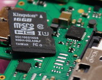
The resistor is REALLY small. The second one from the left in front of the small chip needs to be replaced. And yes, that's a Micro-SD Card to show the size
Fun fact: The third resistor from the left is actually 90° rotated. That's from the pick and place machine It sometimes happens and is the case on multiple PCBs. That's not a problem though, just a fun fact.
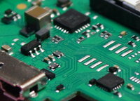
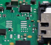
Here are two pictures of the desoldered resistor.
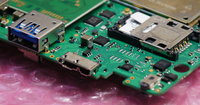
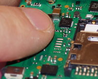
And here's the result: The new capacitor is in there. And my index finger once again shows how small those resistors are.
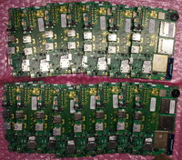
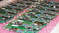
Well, these boards have all been modified - so let's start to turn these little ones into prototypes this week, right?
Now, let's start with the real assembly!
The Lid
The first thing that needs to be assembled is the lid.
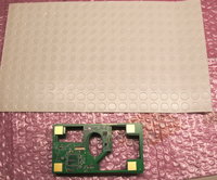
Let's start with a sheet of bumpers and a bunch of LCD PCBs.
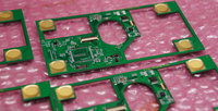
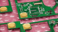
These rubber bumpers are being sticked on the PCBs.
There are two reasons we're doing this with bumpers and not directly inside the plastic:
1. You would see marks on the outer side of the lid if this would be done inside the plastics, which we want to prevent.
2. When you push too hard with the stylus onto the touchscreen, the soft rubber will cushion that a bit and prevent damage.
BTW: The mass production LCD PCBs will look a bit simpler. The solder pads for the once-planned rotator chip will be gone as well as the ones for the other display we looked into. The 0R resistors in the middle of the rotator chip area will also be gone.
Next, we'll need the LCDs.
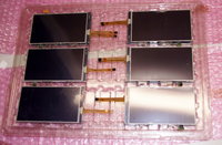
They come on trays - these are actually LCDs from the mass production batch, no prototypes anymore.
Now we'll connect the LCDs to the LCD PCBs:
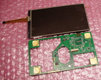
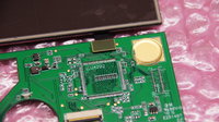
Simply plugging in the small connector...
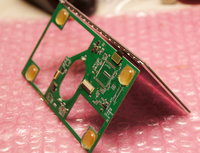
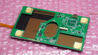
... and simply wrapping the flex cable around the PCB, so that the LCD is in front of the LCD PCB.
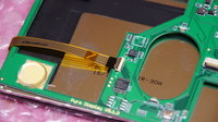
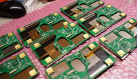
Connecting the touchscreen - and then we're done
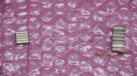
Now, here's a bunch of magnets. I've got two different sizes, as I need to test which ones are strong enough to reliably trigger the lid switch. These are some neat NeoDym-Magnets.
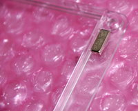
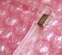
Here they are, glued to the case.
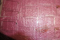
And a bunch of transparent cases with magnets - hard to see, due to the transparency, eh?
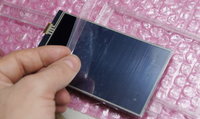
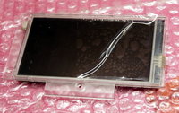
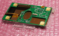
Next step: Putting the pre-assembled LCDs with the PCB into the case. We need to lift the protective foil a bit and put it in front of the case - otherwise, you could have a hard time removing it once the unit is assembled (as the foil would be below the bezel...)
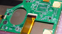
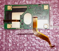
Now it's time to connect the LCD cable.
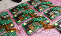
And here we are - 10 almost-finished lids!
Now we only need to roll the cable and put the backside of the lid on.
I couldn't do this today, as I noticed that I don't have the metal logo plates here (they're in the office, and I*m at home). While these will be glued in by the factory for the mass production, I need to do this myself for the prototypes.
I'll continue the assembly and picture posting tomorrow - so stay tuned for updates here at this thread
And sorry again for the delay - I really needed a bit of time to recover from all the stuff that happened. I'm only a dragon like everyone else
UPDATE
2019-03-12:
As promised, here is the continuation of our assembly journey
As mentioned, this next step won't be necessary for the mass production (as the metal pieces will be sticky on one side, so no glue is needed), but for the prototype production, it is necessary.
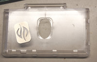
Here is the lid and the metal part of the logo.
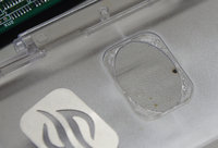
Let's put in some glue.
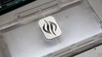
And push the logo firmly on top of that. First step done!
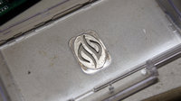
Then we need to put some glue on the metal logo.
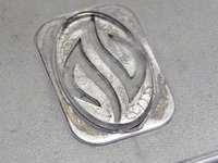
Put in the logo (which will be milky-white transparent in the final unit).

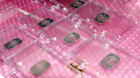
And here they are! The lids and the logo!
As the glue needs to dry first, I couldn't do anymore right now. But the journey will continue!
Aaaaand on we go.
UPDATE
2019-03-20:
I was a bit stupid - as you can see, I connected the LCD cables first and put the screen and PCB into the lid frame.
That's how it worked for the Pandora - but not with the Pyra.
With the Pyra, assembly works better like this:
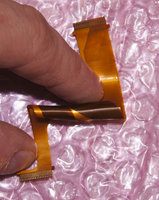
First we roll the cable.
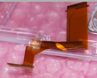
Then we slide it through a tiny slit which is in the case - it's invisible unless you know it's there.
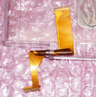
That's how it looks like once it's through.
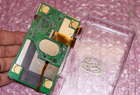
THEN we connect it to the display board!
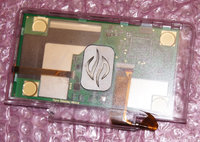
And put it inside the backside of the lid.
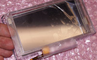
And after that, the front cover is being put on.
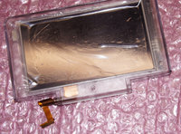
Done! It clicks in on the right and top...
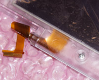
... and needs screws on the bottom and left.
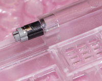
Next, we put the hinge into the keyboard-case-part.
This is where it needs to be pushed all the way in...
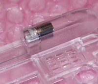
... which looks like that.
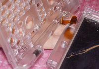
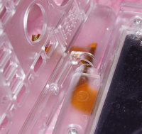
Then we slide the LCD Cable into another slit which is in the keybard part.
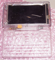
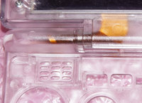
And here's the finished part!
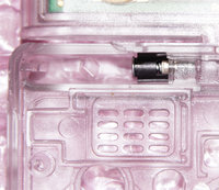
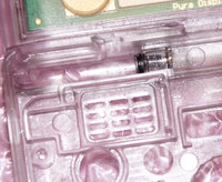
Now the hinge is being pushed back from the inside into the lid.
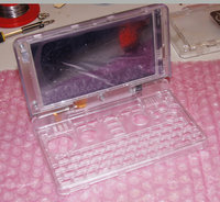
Done! Here is the fully assembled lid with the basement.

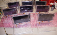
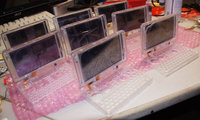

And, of course, I needed to do more than just one
That's it for today... hopefully, I can continue soon. 47 Pictures already, whew
UPDATE
2019-03-26:
Found some time to move forward
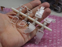
Now, we need these rubber parts. They are used for sealing the speakers.
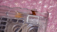
First some rubber for padding...
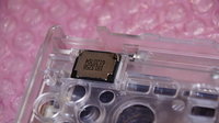
Then the speaker on top.
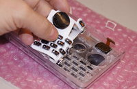
Now we simply put in the keymat.
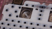
And the discs for the Nubs!
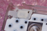
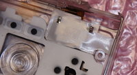
Then both speakers will get the sealing put on top.
Please note: This will probably change for the mass production. It doesn't really make sense having extra rubber parts for sealing the speakers when we already have a silicon keymat.
The keymat will most probably change so that they will have this sealing included - but that's currently being discussed. I will let you know more about it soon.
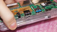
Now it's time to put in the PCB!
When it's inserted, the nub discs need to be rotated until they fall onto the nubs. Works like a charm
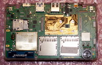
Here's the PCB inside the case, on top of the keymat and speaker sealing
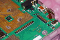
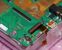
Next: Clip in the LCD Cable

From the front, the unit looks like it's finished already
Next steps (hopefully coming soon): Put in the heatsink and heatpipe together with the CPU-Board - and close everything!
I realized I need to order some more heatsinks to build the prototypes, but that's not a big deal, as I can put them in after I ran the tester software on them.
See you next time!
UPDATE
2019-04-15:
Okay, since I received the remaining stuff I was still in need of, I can finish with the prototype assembly.
So here's the next set of pictures
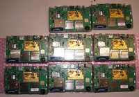
So, here we are. Eight prepared prototypes. Why eight? Well, I had two of the ten lying at work for some tests (so I couldn't include them), and I'm saving the remaining PCBs to use in the revised cases
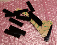
Now it's time to move the heat away from the CPU.
These are standard heatpipes that can be easily bought in exact that size.
Remember the custom cutout I posted somewhere? Well, this is the same material, but to save some time (and to check whether our custom cutout and the readily available stripes make a big difference), I used these this times.
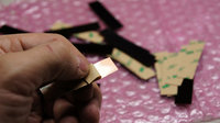
Below the tape, they expose copper (and some self-adhesive glue).
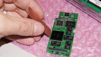
We simply need to put these on the OMAP...
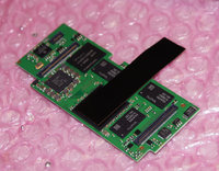
... which looks like this.
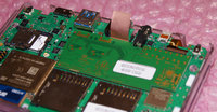
Then put the CPU board into the mainboard. As you can see, the stripe is ALMOST fitting perfectly without any modification. Our custom cutout part will - of course - fit better, but who knows if we need it
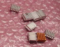
Next, we got the heatsinks. The copper one is bought as is, whereas the aluminium ones have been bought as stick and manually cut by me (yeah, I know I did a bad job with that one )
)
Buying them as sticks and cutting them with a machine is simple and accurate, so if that works better than the available ones, I'm happy to do that. But that's what we need to test
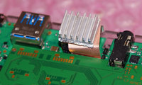
So here is the heatsink on top of the copper strip coming from the OMAP.
It sits directly above the USB port.
As said, the standard strip doesn't fit perfectly, as you can see here
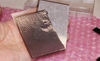
Next, we have something I'd like to try out: Thermal Insulators.
This thin self-adhesive material is said to isolate heat - in theory, you should be able to put this on a 100°C hot stove plate and easily touch it with your fingers!
As we need to keep the CPU heat away from the battery, this might be a solution!
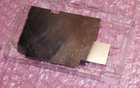
So far, as an alternative, we used lasercut 0.4mm thick metal plates - but of course, these weigh more than the other ones and they heat up over time, so maybe that thermal insulator is working better? I'll find that out
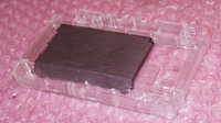
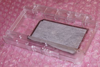
This is how the case looks when the material is applied.
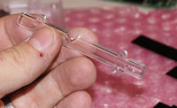
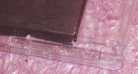
Next step is top put the stylus holder into the case. It's simply plugged in. Done.
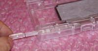
Then the stylus snaps in nicely
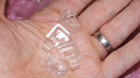
Time for the shoulder buttons. As you know, these are currently being worked on, so this part might change a bit.
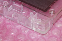
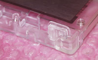
Then we put in both shoulder buttons on both sides.
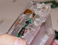
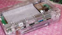
And it's time to assemble both sides!
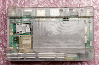
Screw it together...
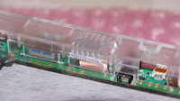
Done! Here you can see the heatsink sitting on top of the USB port.
We can also add a second one on the second port (using our custom-cut material), but according to our simulations, a second heatsink won't help much as there's only so much heat that can move through the heat pipe.
But I'll test that, of course
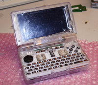
And here's the unit fully assembled
What a journey
Now I need to assemble the remaining ones as well, and then it's time to do the test-run!
UPDATE:
Almost forgot! I assembled more of them!
Here's the picture:
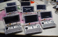
That's about half the prototypes I have, so I can assemble at least 9 more.
Time to continue work on the tester SD Card and test these little babies
Well, the current delay in prototypes building can be blamed on me - not any company or anyone else.
I've had a few rough weeks. First a colleague with whom I've worked for 20 years now has suddenly died due to a heart attack - then I catched a cold (maybe even the flu)... and while I'm usually recovering within 2 - 3 days, this time, it took more than 2 weeks until I fully recovered.
I tried to work on the prototypes - but literally fell asleep in front of them, which wasn't helpful
Maybe it was also a small burnout, who knows. But I guess it was all just a bit too much. A lot of work, death of a colleague which also leads to some demotivation, flu season... all that added up and took its toll.
Anyways, I gave myself some time to recover, as it won't help ANYONE if I continue working in Zombie mode, and it seems like I've fully recovered now, as I'm feeling fine and FINALLY started to work on the prototypes this weekend!
I hope you can understand that
Now, onto the important stuff: The news!
1. The cases
While the new company has already done some tweaks and design changes, they didn't have too much time as they had a huge project by one of their biggest customers which had to be done within a timeframe. They already told me that when I was visiting.
Well, the deadline for that ended last Friday - which means that they can now fully work on the Pyra case.
I can't wait to see the fixes they'll do
2. Small change for the keymats
The manufacturer of the keymats ran into an unexpected small issue while doing the mass production run: It was nigh impossible to prevent visible air bubbles inside the glue when attaching the keycaps.
That's why they're changing the design of the plastic caps so that they will stay affixed on top of the mat without glue.
Everything else stays the same. As soon as I know more, I'll let you know.
3. Prototype building
Finally, long overdue, the prototypes are being assembled by me.
And while I won't do a video (as such a setup is too complex and just hinders the assembly), I'll do a LOT of pictures for you to enjoy, basically a step-by-step guide on how the units are assembled!
I will post these pics here in this thread and will try to update it daily, as I continue to assemble the prototypes.
First some pictures which don't have anything to do directly with the assembling of the prototypes:
One resistor had a wrong value and needed to be replaced. Does anyone remember how MWeston had to replace over 400 resistors to fix Wifi on the first-built Pandoras...?
Yeah, we had something similar - though luckily, we noticed it before the mass production. This wrong resistor value limited the power input of the USB port to 1.5A - which caused a slower charging.

The resistor is REALLY small. The second one from the left in front of the small chip needs to be replaced. And yes, that's a Micro-SD Card to show the size
Fun fact: The third resistor from the left is actually 90° rotated. That's from the pick and place machine


Here are two pictures of the desoldered resistor.


And here's the result: The new capacitor is in there. And my index finger once again shows how small those resistors are.


Well, these boards have all been modified - so let's start to turn these little ones into prototypes this week, right?
Now, let's start with the real assembly!
The Lid
The first thing that needs to be assembled is the lid.

Let's start with a sheet of bumpers and a bunch of LCD PCBs.


These rubber bumpers are being sticked on the PCBs.
There are two reasons we're doing this with bumpers and not directly inside the plastic:
1. You would see marks on the outer side of the lid if this would be done inside the plastics, which we want to prevent.
2. When you push too hard with the stylus onto the touchscreen, the soft rubber will cushion that a bit and prevent damage.
BTW: The mass production LCD PCBs will look a bit simpler. The solder pads for the once-planned rotator chip will be gone as well as the ones for the other display we looked into. The 0R resistors in the middle of the rotator chip area will also be gone.
Next, we'll need the LCDs.

They come on trays - these are actually LCDs from the mass production batch, no prototypes anymore.
Now we'll connect the LCDs to the LCD PCBs:


Simply plugging in the small connector...


... and simply wrapping the flex cable around the PCB, so that the LCD is in front of the LCD PCB.


Connecting the touchscreen - and then we're done

Now, here's a bunch of magnets. I've got two different sizes, as I need to test which ones are strong enough to reliably trigger the lid switch. These are some neat NeoDym-Magnets.


Here they are, glued to the case.

And a bunch of transparent cases with magnets - hard to see, due to the transparency, eh?


Next step: Putting the pre-assembled LCDs with the PCB into the case. We need to lift the protective foil a bit and put it in front of the case - otherwise, you could have a hard time removing it once the unit is assembled (as the foil would be below the bezel...)


Now it's time to connect the LCD cable.

And here we are - 10 almost-finished lids!
Now we only need to roll the cable and put the backside of the lid on.
I couldn't do this today, as I noticed that I don't have the metal logo plates here (they're in the office, and I*m at home). While these will be glued in by the factory for the mass production, I need to do this myself for the prototypes.
I'll continue the assembly and picture posting tomorrow - so stay tuned for updates here at this thread
And sorry again for the delay - I really needed a bit of time to recover from all the stuff that happened. I'm only a dragon like everyone else
UPDATE
2019-03-12:
As promised, here is the continuation of our assembly journey
As mentioned, this next step won't be necessary for the mass production (as the metal pieces will be sticky on one side, so no glue is needed), but for the prototype production, it is necessary.

Here is the lid and the metal part of the logo.

Let's put in some glue.

And push the logo firmly on top of that. First step done!

Then we need to put some glue on the metal logo.

Put in the logo (which will be milky-white transparent in the final unit).


And here they are! The lids and the logo!
As the glue needs to dry first, I couldn't do anymore right now. But the journey will continue!
Aaaaand on we go.
UPDATE
2019-03-20:
I was a bit stupid - as you can see, I connected the LCD cables first and put the screen and PCB into the lid frame.
That's how it worked for the Pandora - but not with the Pyra.
With the Pyra, assembly works better like this:

First we roll the cable.

Then we slide it through a tiny slit which is in the case - it's invisible unless you know it's there.

That's how it looks like once it's through.

THEN we connect it to the display board!

And put it inside the backside of the lid.

And after that, the front cover is being put on.

Done! It clicks in on the right and top...

... and needs screws on the bottom and left.

Next, we put the hinge into the keyboard-case-part.
This is where it needs to be pushed all the way in...

... which looks like that.


Then we slide the LCD Cable into another slit which is in the keybard part.


And here's the finished part!


Now the hinge is being pushed back from the inside into the lid.

Done! Here is the fully assembled lid with the basement.


And, of course, I needed to do more than just one
That's it for today... hopefully, I can continue soon. 47 Pictures already, whew
UPDATE
2019-03-26:
Found some time to move forward

Now, we need these rubber parts. They are used for sealing the speakers.

First some rubber for padding...

Then the speaker on top.

Now we simply put in the keymat.

And the discs for the Nubs!


Then both speakers will get the sealing put on top.
Please note: This will probably change for the mass production. It doesn't really make sense having extra rubber parts for sealing the speakers when we already have a silicon keymat.
The keymat will most probably change so that they will have this sealing included - but that's currently being discussed. I will let you know more about it soon.

Now it's time to put in the PCB!
When it's inserted, the nub discs need to be rotated until they fall onto the nubs. Works like a charm

Here's the PCB inside the case, on top of the keymat and speaker sealing


Next: Clip in the LCD Cable

From the front, the unit looks like it's finished already
Next steps (hopefully coming soon): Put in the heatsink and heatpipe together with the CPU-Board - and close everything!
I realized I need to order some more heatsinks to build the prototypes, but that's not a big deal, as I can put them in after I ran the tester software on them.
See you next time!
UPDATE
2019-04-15:
Okay, since I received the remaining stuff I was still in need of, I can finish with the prototype assembly.
So here's the next set of pictures

So, here we are. Eight prepared prototypes. Why eight? Well, I had two of the ten lying at work for some tests (so I couldn't include them), and I'm saving the remaining PCBs to use in the revised cases

Now it's time to move the heat away from the CPU.
These are standard heatpipes that can be easily bought in exact that size.
Remember the custom cutout I posted somewhere? Well, this is the same material, but to save some time (and to check whether our custom cutout and the readily available stripes make a big difference), I used these this times.

Below the tape, they expose copper (and some self-adhesive glue).

We simply need to put these on the OMAP...

... which looks like this.

Then put the CPU board into the mainboard. As you can see, the stripe is ALMOST fitting perfectly without any modification. Our custom cutout part will - of course - fit better, but who knows if we need it

Next, we got the heatsinks. The copper one is bought as is, whereas the aluminium ones have been bought as stick and manually cut by me (yeah, I know I did a bad job with that one
Buying them as sticks and cutting them with a machine is simple and accurate, so if that works better than the available ones, I'm happy to do that. But that's what we need to test

So here is the heatsink on top of the copper strip coming from the OMAP.
It sits directly above the USB port.
As said, the standard strip doesn't fit perfectly, as you can see here

Next, we have something I'd like to try out: Thermal Insulators.
This thin self-adhesive material is said to isolate heat - in theory, you should be able to put this on a 100°C hot stove plate and easily touch it with your fingers!
As we need to keep the CPU heat away from the battery, this might be a solution!

So far, as an alternative, we used lasercut 0.4mm thick metal plates - but of course, these weigh more than the other ones and they heat up over time, so maybe that thermal insulator is working better? I'll find that out


This is how the case looks when the material is applied.


Next step is top put the stylus holder into the case. It's simply plugged in. Done.

Then the stylus snaps in nicely

Time for the shoulder buttons. As you know, these are currently being worked on, so this part might change a bit.


Then we put in both shoulder buttons on both sides.


And it's time to assemble both sides!

Screw it together...

Done! Here you can see the heatsink sitting on top of the USB port.
We can also add a second one on the second port (using our custom-cut material), but according to our simulations, a second heatsink won't help much as there's only so much heat that can move through the heat pipe.
But I'll test that, of course

And here's the unit fully assembled
What a journey
Now I need to assemble the remaining ones as well, and then it's time to do the test-run!
UPDATE:
Almost forgot! I assembled more of them!
Here's the picture:

That's about half the prototypes I have, so I can assemble at least 9 more.
Time to continue work on the tester SD Card and test these little babies
Last edited:

