Bacteria's Gp2X Mod - Project 1


bacteria

Modder & Portablizer
Joined
Jan 12, 2006
Messages
1,119
Location
Hampshire, UK.
Website
moddedbybacteria.wordpress.com
As promised, this is the first of two GP2x projects, which will be catalogued here.

This project takes a fully working GP2x, will implement a d-pad, the case will be resprayed, the back of the case will be modded to take a li-ion cell and recharge jack.

This project will be sold, or at least offered for sale when finished, and a percentage of that will go to Dave18 as he donated his working but broken GP2x F200 to me, which i'll use for Project 2. Dave18 didn't want anything for his system, I thought however it only fair to give him a piece of the profit from the sale on this unit!

The F200 (Project 2) will be for my own use, so will keep it.

So, onto the guide. I'm going to make it easy to follow so others can hopefully copy the work.

In saying that, some parts like opening up the system are pretty straightforward and been covered other times on this forum.

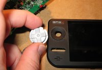
Using one of these dpads, got it ages ago from a generic controller. D-pad crosses are usually crosses, however some are on circular blocks like this one.

If you use a normal d-pad cross, a good idea would be to cut out the hole for the cross to go through and move about freely inside, cut the perimeter of the section into a circle, and mount on top of the GP2x case - or of course you could make it integrated and use filler, etc.

Good d-pad crosses are ones from GameCube, Gameboy, Gameboy mini, or as a maximum size, from a NES controller.

I selected the d-pad below from my small box of d-pads as it was just the right size, could retain GP2x case and just cut out the circular hole the old joystick came from, cutting close to the edge of the raised outer part.

52jk1s.jpg


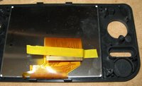
So, the GP2x was opened carefully, buttons removed, and the ribbon cable to the screen removed by gently lifting the edge of the brown plug holding the ribbon in place on the GP2x board, using edge of thumb nail - be gentle. The ribbon was then gently attached to the back of the screen with a thin piece of electrical tape so it can be removed easily - point is to protect the ribbon cable from damage. The other reason to separate the screen from the motherboard is so it is easy to remove the joystick and build a replacement d-pad area (with rubber topped tact switches).

Removed the "T" shaped small plastic piece above the cut-out circle as not needed and gets in the way.

ixtr8m.jpg


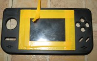
Decided not to remove the perspex screen at the front of the case so as not to introduce dust to the screen, also, the case will be spray painted metallic black, so may as well just use electrical tape to protect the screen from the paint when I get to that stage.

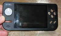
Here are two pics of the d-pad in place. D-pad looks nice and moves freely. The d-pad will also be spray painted in metallic black of course.

2s691tv.jpg


210g27t.jpg


Before the case is spray painted, going to tape over the screen, and give the case outer a quick and light sanding, to remove any light scratches and also help the spray paint make good on the case.
 

Attachments

  • 52jk1s.jpg
    52jk1s.jpg
    29.9 KB · Views: 346
  • ixtr8m.jpg
    ixtr8m.jpg
    38.5 KB · Views: 342
  • 2s691tv.jpg
    2s691tv.jpg
    23.2 KB · Views: 478
  • 210g27t.jpg
    210g27t.jpg
    31.7 KB · Views: 467
Spray painted the buttons, case front and d-pad, metallic black - looks lovely!

Up to that stage (got to wait for it to dry, etc):

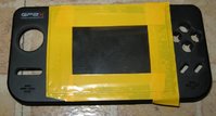
Put a piece of acetate in the middle of the screen so easier to remove the electrical tape after painting; stuck down some electrical tape, then using a sharp craft knife, cut off the surplus from the window area.

9vfg9y.jpg


sq3ti0.jpg
 

Attachments

  • 9vfg9y.jpg
    9vfg9y.jpg
    26.2 KB · Views: 389
  • sq3ti0.jpg
    sq3ti0.jpg
    35.2 KB · Views: 394
I just bought a GP2X on eBay as I sold my first GP2X three years ago. Great to see your mod and I will watch it progress. Back when I had my first 2X I had problems with the stick. Sure wish I could implement a good D-Pad replacement myself. :D
 
I'm hoping the d-pad implementation in this project will be straight forward enough for anyone to follow.

Case front is looking georgeous at the moment, the metallic black paint looks nice - just applied the metallic spray paint sealer to the case. Will need a day or two to dry so it can be handled. Might even start Project #2 in the interim.
 
My stick cap just cracked (Again! Second one since '06) so I will follow this too.
I have a GBC d-pad I could use if I decide to try this for myself. ^^
 
I will try to keep it so, if there are any questions along the way, please ask.

Update:

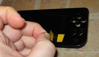
Easy to remove the electrical tape to reveal the protected screen underneath.

bjefxc.jpg


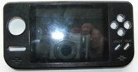
Here's what the front looks like now - after the paint job.

svjj9j.jpg
 

Attachments

  • svjj9j.jpg
    svjj9j.jpg
    40.5 KB · Views: 335
  • bjefxc.jpg
    bjefxc.jpg
    22 KB · Views: 343
bacteria said:
I'm hoping the d-pad implementation in this project will be straight forward enough for anyone to follow.

I've never tried any mod before but you are making it really simple to understand, so much that I know I will definitely try to do it. Thanks a lot and keep it up!

Also that metallic black case is looking great indeed.
 
Last edited by a moderator:
Excellent!

Small upload at the moment:

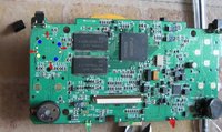
Used a smallish pair of snippers to snip off the pins off the joystick to release it from the board. No point desoldering the joystick, we don't need it, the board is multi layer and if you damage the pins you can damage the workings of the joystick on the board. Snip off the pins at the base, and then use a Dremel to flatten the places the pins were on so the area is flat on the board.

15wceqb.jpg


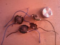
Proof of concept - put the rubber tact switches under the d-pad and it appears there is plenty of space under there for the assembly - in fact, may need to lift it up a bit!

15gvyvs.jpg


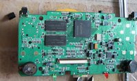
Back to the board - pinout - red arrows are the up, down, left and right. The blank pins are diagonals, which we don't want to use; yellow is center click and blue are groundings. I think this is right, didn't think to test with the continuity tester before I cut nearly all the pins off the board first!

23jq2xx.jpg


Will need to put a centre-push button elsewhere in case of course, which isn't any issue at all.


Making this how-to guide simple to follow - you guys can install your own d-pad for nearly no cost: you just need 4 rubber tact switches, a d-pad cross (if you only have normal "X" ones, then also a piece of strong plastic about 1mm thick); then for tools, just snippers, soldering iron and solder, drill/Dremel, a little wire; maybe glue (let's see). Very cheap. If anyone doesn't want to do the work, I will take commissions at the end of the project if anyone needs it done; however frankly, I want to make this mod so simple that anyone can do it themselves...
 

Attachments

  • 15wceqb.jpg
    15wceqb.jpg
    71.8 KB · Views: 377
  • 15gvyvs.jpg
    15gvyvs.jpg
    30.2 KB · Views: 324
  • 23jq2xx.jpg
    23jq2xx.jpg
    72.3 KB · Views: 340
bacteria said:
Excellent!

Small upload at the moment:

Used a smallish pair of snippers to snip off the pins off the joystick to release it from the board. No point desoldering the joystick, we don't need it, the board is multi layer and if you damage the pins you can damage the workings of the joystick on the board. Snip off the pins at the base, and then use a Dremel to flatten the places the pins were on so the area is flat on the board.

-

Proof of concept - put the rubber tact switches under the d-pad and it appears there is plenty of space under there for the assembly - in fact, may need to lift it up a bit!

-

Back to the board - pinout - red arrows are the up, down, left and right. The blank pins are diagonals, which we don't want to use; yellow is center click and blue are groundings. I think this is right, didn't think to test with the continuity tester before I cut nearly all the pins off the board first!

-

Will need to put a centre-push button elsewhere in case of course, which isn't any issue at all.


Making this how-to guide simple to follow - you guys can install your own d-pad for nearly no cost: you just need 4 rubber tact switches, a d-pad cross (if you only have normal "X" ones, then also a piece of strong plastic about 1mm thick); then for tools, just snippers, soldering iron and solder, drill/Dremel, a little wire; maybe glue (let's see). Very cheap. If anyone doesn't want to do the work, I will take commissions at the end of the project if anyone needs it done; however frankly, I want to make this mod so simple that anyone can do it themselves...

Hey Bacteria,

Excellent work, this by far is the most easiest d-pad replacement i've seen, kudos on just snipping of the joystick pins (never thought of that :) ).

I will definetly be attempting this mod, but I need a good d-pad.

If you have any spare d-pad(s) and you don't mind giving away (most appreciated of course), please can you send me one. Very hard to find the right one.

Looking forward to how you wire up the tact switches to the board and d-pad.

Keep up the good work.

Irefan
 
Last edited by a moderator:
irefan - i'll make a deal with you - join my forum, be active in it and be a good beneficial member to have around; and also start a topic there with your GP2x mod thread so you can post your work in progress onto (and copy the build thread here too of course), and i'll not only give you a free d-pad cross ("+" cross one, not in a circle around it as per mine) but also give you four rubber topped tactile switches (like i'll be using) and one topped normal and small tact switch so you can do it; and free postage! PM me...

I don't have many other d-pads spare just a couple more, but if anyone else is looking to do the mod, and agree to the above, please let me know! (if I run out of d-pads I can always just send some of the tact switches; you can make your own d-pads with perspex if you like anyway!)

In principle, this could be a very easy d-pad mod indeed; as the usual method is to use and trim a contact board, etc, rather than make a small integral unit.
 
Changed tactics - making this a video log guide for the project. It isn't a large project, and "being shown" is always easier to follow than lots of pics.

Made first 4 minutes of video; taking up to the d-pad in and installed.

Got the d-pad assembly working fine, frankly, it was a doddle to get to this stage. Anyone who wants to make their own can do so easily with the video guide...

ztjhnk.jpg


And a pic of it being pressed:

ve2hwy.jpg


I'm making a video guide to accompany this mini project which i'll present at the end of the work.

Next step, attach the buttons, put the ribbon cable back, close case top up; wire the d-pad connections, test; then do the case backing (li-ion battery mod). Might have the work done by the end of the week, plus paint drying time...
 

Attachments

  • ztjhnk.jpg
    ztjhnk.jpg
    12.5 KB · Views: 308
  • ve2hwy.jpg
    ve2hwy.jpg
    9.1 KB · Views: 311
Hi Bacteria thank you so much for this i am going to give it a go. :D I have found an old N-Gage D pad and its the perfect size. Where can i get the rubber tact switches from. I have found some rubber contact buttons (see pic) may have to trim boards so they fit will they do the job. :D
5jv5tj.jpg
 

Attachments

  • 5jv5tj.jpg
    5jv5tj.jpg
    53.5 KB · Views: 331
bacteria said:
Making this how-to guide simple to follow - you guys can install your own d-pad for nearly no cost: you just need 4 rubber tact switches, a d-pad cross (if you only have normal "X" ones, then also a piece of strong plastic about 1mm thick); then for tools, just snippers, soldering iron and solder, drill/Dremel, a little wire; maybe glue (let's see). Very cheap. If anyone doesn't want to do the work, I will take commissions at the end of the project if anyone needs it done; however frankly, I want to make this mod so simple that anyone can do it themselves...

What?! Forgot the duct tape? :p


irefan said:
Hey Bacteria,

Excellent work, this by far is the most easiest d-pad replacement i've seen, kudos on just snipping of the joystick pins (never thought of that :) ).

Same here. Somehow I thought you would desolder it and that's one of the things preventing me from doing a d-pad mod, but this gets another thing out of the way.


[quote name='bacteria']
I don't have many other d-pads spare just a couple more, but if anyone else is looking to do the mod, and agree to the above, please let me know! (if I run out of d-pads I can always just send some of the tact switches; you can make your own d-pads with perspex if you like anyway!)
[/quote]

Ahh, such a shame I don't have internet at home right now (and probably won't for a bit longer which won't help me in being a "beneficial member"), but I will at least try to join your forum and document my mod when I start it. Gotta go right now so, it will have to be another day though... :p
 
Last edited by a moderator:
Good, it would be great to have some GP2x mods on my forum from various members!

I just figured that we aren't relocating the joystick and don't want it anyway, so no point desoldering it off the board, after all, removing it that way is not easy, and as the board is multi layer, it would be easy to damage part of a trace inside and damage the board; so what's the point! A pair of snippers and 5 seconds is all that's needed to remove it!

If anyone needs a spare joystick or joystick cap, i'll send one for the cost of postage (and PayPal fees); PM me if interested. You can easily snip off your existing joystick, apply flux to the joystick pins and your contacts, and solder on a new one - easy.
 
I trimmed the tiny rubber button boards and they still do not fit close enough together. :( So i need to get myself some rubber tact switches where do you get yours from bacteria?. Once i have all the components i will start the mod and upload pics as i go. :D
 
Back
Top