Bacteria's Gp2X Mod - Project 1


Ok guys - help needed please!

Got the d-pad working beautifully, tested in T-mode lovely!

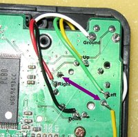
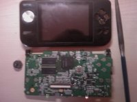
The problem is that the center click doesn't work. I've got a GP2x-F100( B ) model, and have checked and double checked to confirm the two pins responsible for center click, as marked by the purple arrow in the pic below.

2vctjyc.jpg


Problem is, as you can see, the top of those two connections (marked on the pic with the arrows) is connected to ground (you can see that if you look closely), which it isn't on the joystick. I have sanded down the reverse side of the board and confirmed that the only way the pin is connected to ground is on the back of the board.

This seems to indicate that this GP2x doesn't use the center click function, as whatever I press in T-mode doesn't give a center click result - the center click does not use grounding to work.

So guys, am I missing something, or did this version of GP2x not have a working center click? I tried pressing both volume buttons to get center click, in case it does that like on the F200, but made not difference.

Ideas? At the moment, looks like this GP2x can't run with a center click feature! (didn't check to see if it did before, not used the GP2x for ages). Also, and relevantly, do the GP2x emulators use or need to use the center button (older emulators did)? What if any restrictions are there with no center click?
 

Attachments

  • 2vctjyc.jpg
    2vctjyc.jpg
    101.5 KB · Views: 382
Those wires look a bit thick will the shoulder button miss them i think i will use some ribbon cable ;)
I have a f100B and the stick click does work but i have never had to use it in any of the emulators.
 
Wires are just under 1mm thick, and flexible. Works fine.

If emulators don't need center click, there is no issue?

Can't work out why the function doesn't work though!

Looking on the Wiki HERE it doesn't look like the center button is used at all - is this right, what is it useful for?
 
Excellent, thanks for the confirmation. There was no reason on the board it wouldn't do the center push facility; as it is confirmed from the above, and the Wiki on emulators for the GP2x, that it isn't needed, I won't be concerned! (spent most of the afternoon trying to resolve the issue!).

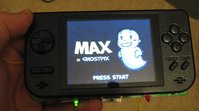
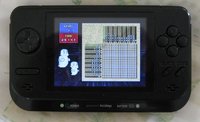
BTW - here's the pic so far of the front (finished):

2czpky.jpg


Just need to put a PSP Li-ion battery in the back and do the case backing now.
 

Attachments

  • 2czpky.jpg
    2czpky.jpg
    27 KB · Views: 608
Made a great discovery - added this in a short video clip to the video i'm compiling, however showing this in pic form here too:

We all know the battery life from two AA NiMH cells sucks on the GP2x.

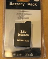
I bought a PSP battery for my PSP a while back and being a Chinese rip-off it didn't work; the battery is good but clearly Sony have built in some software to detect on their PSP3000 model that the battery is no a genuine Sony one, so won't work with it.

4hs4gi.jpg


The battery is a 3.6 amp Li-ion battery at 3.7v, so lasts well on the GP2x, not sure how long, but I read somewhere someone was claiming about 10 hours between charges?

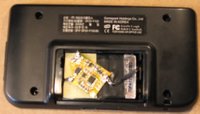
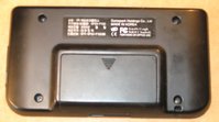
Anyway, open the battery up by removing the plastic casing, move the battery protection circuit board a bit so it doesn't overhang the battery, remove the metal battery tabs from inside the GP2x case backing; you will see, the battery sits in place of the two AA cells space: and the lid shuts! All that is needed therefore is a small female plug to connect to an external battery charger! No more modding needed!

16c7tb6.jpg


35lhgt1.jpg


Great discovery, yes?
 

Attachments

  • 4hs4gi.jpg
    4hs4gi.jpg
    35 KB · Views: 294
  • 16c7tb6.jpg
    16c7tb6.jpg
    23.5 KB · Views: 434
  • 35lhgt1.jpg
    35lhgt1.jpg
    22 KB · Views: 299
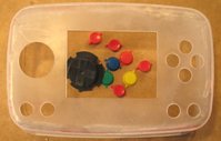
Made casing for project #2... will spray paint this and start to fill it with the other GP2x system (remember, I said I was doing two GP2x projects?). Going to leave the second one to the end though to reveal it fully...

1 litre tupperware boxes, bottom cut out, 2mm perspex cut and hot glued to replace it, sanded very smooth against the side of the case, bondo filler used, electrically sanded very smooth, buttons and screen cutout - took only two and a half hours of quick labour. The 1 litre case is just a little bigger than the GP2x case, and allows me to put in larger buttons and space them better...

w1cyab.jpg
 

Attachments

  • w1cyab.jpg
    w1cyab.jpg
    25.1 KB · Views: 304
Well no turning back sniped off the sick and used a file to make the hole for the N-Gage D pad :eek:

dfbv9z.jpg


Sorry about the sh*t pic quality.
 

Attachments

  • dfbv9z.jpg
    dfbv9z.jpg
    18 KB · Views: 322
The 1 litre case is just a little bigger than the GP2x case, and allows me to put in larger buttons and space them better...

And if there's space left over, you can keep your sandwiches in there :p

Seriously, that's an interesting mod - can't wait to see the finished article :)
 
Great second mod so far, I like how it looks. :) And after finally getting my SD card issue sorted with my new 2X, I've realised yet again how poor the joystick is. Playing Beats of Rage was a chore in particular. Guess it's time to learn how to use a soldering iron or whatever these kind of DIY projects require.
 
Soldering on the project (#1) is very basic indeed; show part of what is needed in the video being compiled.

Project #2 (with the tupperware box) needs the SD card relocated and the USB (what is that used for BTW - can't you just use the SD card for everything?), also thought of putting on a heatsink onto the processor so it can overclock better...

Not making a worklog for the #2 as it isn't something others will probably want to do, more likely to just keep the case intact and change the battery and d-pad instead (nearly done with these video clips). I've therefore decided to complete both projects and in the last minute or so of the video also present #2 for view. Used just under 7 mins of video time so far, so have 3 mins left (YouTube limit is 10 mins for a video); leaves plenty of time remaining to cover the rest of #1 and then #2.

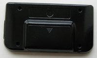
Case backing for #1 is dry and looks lovely. It is spray painted in metallic black.

2ika4vr.jpg


I will mention one exclusive - the tupperware GP2x will not be done in just black or my normal red and black - going to use metallic purple for the case and metallic black for the buttons.

BTW - metallic spray paint is fantastic stuff - doesn't wear off things like buttons like it can with normal spray paint, and dries far quicker. You need to use a metallic spray paint sealer of course, which acts like a varnish.
 

Attachments

  • 2ika4vr.jpg
    2ika4vr.jpg
    21.2 KB · Views: 327
Before you spray paint the multi-coloured buttons on #2, can you show us them as they are now in a built version? I like the idea of multi-coloured buttons in a GP2X. :)
 
The buttons and d-pad are as per the pic in previous post (post #29). I think having all those colours will make it look "kiddie toy", rather than the aim to make it look fairly professional.

Experimenting - had six Li-ions from a couple of years ago when doing the old "Mini" project which I broke apart a while back. The Li-ions were ones described as NDS replacement batteries, 3.7v, some 2000mA and others 1800mA. In reality, I originally put two sets in parallel and two sets in series, to get 7.4v at around 3900mA. The reality though was after a short while, about 55 minutes, driving a PSone screen and plug'n'play game (total probably around 1100mA), the battery protection circuits kicked in, as presumably the voltage was draining. This probably means the Chinese crap NDS batteries were more like around 1100mA not 2000mA as claimed.

Anyway, one of the six cells had swelled in the meantime (ie faulty) so threw it out as they can explode if you try to use a swelled Li-ion cell; leaving me five cells. The GP2x can use 3.7v fine, so in effect, I now have five 3.7v batteries in parallel, which will hopefully give something like 5500mA current; which, if i'm right, might power my second project for (I dunno) 15 hours? If it does, I have space for a 6th cell, so can get one to add to the pack as there is space for them in the case. Could add double that if I wanted. Point is, managed to recycle these crap batteries into something useful! Booted my #1 project just now with this battery pack, out of interest, booted fine and also gave me all three battery life bars.

Spent a while last night putting in holes for the two shoulder buttons into #2's case; need to make a hole for the USB, charger, SD slot, on/off switch, speakers (might have speakers at back of case, not decided yet - going to use larger speakers if the GP2x works with them better. Project #1 will be done in the next hour or two hopefully, and finished; however project #2 will take several more days!

Thinking about it more, I may as well make project #1 into its own video as it is a guide, #2 project will be a different video.

I'll post the video here when done, as well as other places...
 
I think having all those colours will make it look "kiddie toy", rather than the aim to make it look fairly professional.

You mean like the Dreamcast and SNES ;)

I didn't mean leave them permanently - I did say "before you paint them." This is the only chance we'll get of seeing a GP2X with coloured buttons, so I thought I might as well ask. Oh well.
 
Ok, i'll spray paint the casing first then show the system before spray painting the buttons!

On a different note, FINISHED the GP2x project (project #1) it now has a proper d-pad and Li-ion cell. Had no-where to put a stereo jack (using one for the external charger, had to trim inside the battery compartmnent to make space - took the afternoon to do that. Anyway, got lots of pics and video clips, going to have to pick what I want, edit, etc. I want to see how long the battery will last, charged, so charging the cell at the moment (I also want to know how long it lasts for the last video clip too).

I'm making the build process and documentation all on the video, however having to use some stills with wording on, to explain the latter stages.

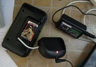
Yes, used a PSP charger (well is it a PSP battery), modded the charger a bit so the charger can still be used to charge a proper PSP battery too. The charger unit is designed to take power input from a PSP wall power adaptor (5v) so that is connected too. The reason I used a stereo jack for recharging a battery is that the battery has three contacts on it, one for positive, one for negative, and the middle one presumably for recharge status. A stereo jack has three connections too.

nx6zw0.jpg


When the system is being used, the original battery cover is on, it has to be off though for the recharge jack to be used - although, I might make a hole in the backing piece and leave the backing closed...

Needs a bit of a dust, etc, but:

34gkqix.jpg


Intention will be to sell this unit as mentioned before; when the video is done, done games testing, etc.
 

Attachments

  • nx6zw0.jpg
    nx6zw0.jpg
    35 KB · Views: 330
  • 34gkqix.jpg
    34gkqix.jpg
    35.7 KB · Views: 321
Great! It will be interesting to see how many bids it gets and the price it gets. Realistically, it will be a few days before I get the time to do these things and ready to post; I want to play with the system for a couple of hours with various emulators, to test it out before selling it - also, to help with the last video clip.
 
Ok, put some emulators on the SD card, loaded up Gradius 3 on the SNES emulator (boy, that works full speed now - not used my GP2x since the end of 2006, judging by my backups), and the battery only lasted 2 hours. Either the battery doesn't hold the amps it claims (possible); or the GP2x takes about the same current on 2.4v as 3.7v. So, i'm going to have to try one more mod on the GP2x - put in a second PSP battery in parallel - if that doesn't yield 4-5 hours playtime, I don't know what will!

I think there is just about enough space to put a second one in the GP2x casing....
 
Back
Top