Share your projects


I've attached v0.000000000000000000000000000000001 of The Journey Home to this post for people to try out if they wish.

How to play: Extract the archive then double click on the HTML file.

How to modify: Either use Twine's import file feature or edit the HTML file directly using your favourite text editor.

License: CC BY-NC-SA 4.0
 

Attachments

  • The Journey Home.zip
    82.6 KB · Views: 453
More from Galaksija "replica" log:
(first part: Here).

2018-11-11
Initial assembly started. Lots and lots of jumper wires, I haven't soldered them all. Going from right to left, jumper wires first, then IC sockets. After I soldered copper wire as jumpers in ZX97Lite clone and it darkened, I decided to use insulated wire with nice green insulation where possible. So, under sockets it's impossible, and under keys too, copper wires from network cable go there.
These nice Tesla green sockets won't fit as it's not too much space between ROM/RAM sockets. I used one in character ROM.
There are more problems than I initially thought. I see that tracks are porous, it's hard to stick solder to them and if it sticks, it sticks to the PCB too. Soldered ROM/RAM sockets, it's hard. The only method to finally stick the socket's pin to track was to install socket, bend pins outwards or inwards as much as possible, brush it with flux and use capillary forces to pull the solder: Heat the pin, push the alloy under it.
Some tracks have visible holes, some have visible links. Before starting it will be needed to clean the situation with an ohmmeter, soldering iron and knife. Tomorrow: CPU region.

2018-11-18
Assembled keys, sockets, jumpers and most resistors and capacitors. There are significant problems with tracks, lots of fixing as they are "porous", so ordinary coating with alloy does not fix the problem. The keys used are a bit different than original, so I had to modify holes and it's impossible to correct their orientation as it was with original computer using a separate plate. It generally looks nicer now, no shorts on RAM/EPROMs, character ROM not tested.

2018-11-20
Assembled everything. Removed more shorted/opened tracks. Startup -> No clock. Removed problem with too big cap in generator circuit, restored broken connection between inverters, clock ran, there even is something like a sync, but nothing more. Found that D0 is shorted with clock and corrected it. Still no result.
No reaction to reset. There are errors on official schematic, especially related to pin numbers on glue logic. Russian schematic (Fifan's) is better, the only mistake seems to be related to data lines on 74LS174 in which two of them are flipped, but on the other side of chip they are flipped too. Additionally something seems to be wrong with resistors for video, so I'll take video from between resistors of a modulator divider. It looks like the machine bursts all components on the same logic levels, so everything goes messy.

2018-11-22
OK, there are probably more bad connections, let's roll heavy cannons now. No boot up and CPU does some babbling on buses, activating RAMs and EPROMs. I decided to buzz through all connections using Russian schematic as a reference. Found that two chips just have no power and quite important connection to move video out is broken. Fixed and tried to boot.
Partial success - there is a READY prompt, but the computer seems not to work stable way - CPU hangs, memory writes are going not where intended, and picture lines are missing, LISTing simple program returns gibberish. Because the clock is derived from a single oscillator, I decided to diagnose the following way:
1. Change CPU. This computer seems to work well with a "80A MME" East German CPU... and no other. Even original Zilog's Z80 and clone with "R" in logo break timings and it crashes before displaying second picture line (ROMs stop to be readable too early).
2. Mess with capacitors. This was a good idea. I had no other 5nF, so hacked 4n7 using soldering iron :). CPU seems to run stable now, but picture is still missing random lines and... it looks like it warms up, after 20-30 seconds it's OK.
3. Mess with generator. Good that I have an oscilloscope.
Now the most important thing to fix this issue: Without oscilloscope, Initiating this computer is just trial and error. Timings are critical, one gate flips too fast (still in datasheet tolerances) and data goes to the wrong place. I have bought a new inverter chip for clock generator as I knew that this is a generator, parasitic capacitances in dirty connections from unsoldered 30 year old chip may kick in, gates have to be fast, don't they? Well, here NOT. The clock for pixel generation just has to be delayed specific amount of time or it will make italics. I finally found a set of logic that works with minimum capacitors added and there is this 30 year old 74LS04. Additionally, my new CD4040 (manufactured 2010) used as clock divider seems to mess timings too (firing interrupts too fast) and I had to use an old Harris chip to make it go properly.
The computer successfully executed a simple arithmetic program for 15 minutes and did not hang! Draws about 0.66A of 5V, so it can be fed using 78L05 regulator.
Summing up: Now I have to find a cheap casing for it.
I got the mainboard laminate from my friend who was working in laminate factory years ago, I also have A4 samples of other laminates, not copper-coated. Maybe I'll make a frame of flat wooden boards, in which the front panel made of laminate sits on junctions in angles, and the mainboard just slides in? Something like this.
 
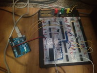
This is a programmable sound generator implemented using TTL chips, and using an arduino for sending commands
The goal is to have 3 pulse channels, 2 triangle channels, and 2 noise channels.

This is a single pulse channel. It can do MIDI notes 57-127, has 16 volume levels, and 12.5% 25% and 50% duty cycle options. (it's basically the same as the NES pulse channels)
PSG.jpg

Here's a video demonstrating the variable duty cycle. The audio is very quiet.
 
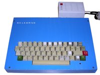
So here is the final version of my Galaksija replica:
galaksija.jpg
(complete build log with photos)

Some time ago I assembled it completely and made casing of wood, made a few programs and tested existing ones.

And here's the most important thing I learned from building:
Adding blue dye to white paint causes it to become blue only to some degree. Adding more dye then will NOT darken the colour, even if the dye itself is darker.
Yes, this was supposed to be dark blue.
And about this poor laminate I mentioned earlier. FR-4 states for "Flame Retardant", and usually is made of glass fiber and epoxy resin, so sometimes it's translated as "Fiber/Resin". This particular factory labeled this laminate as "FR4" because it was "Fenol Resin". For filler, probably paper was used.
 
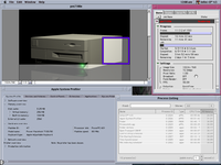
Got a new video in the pipe on the topic of my PowerMac 7100. Doing some rendering on it just for fun.
 

Attachments

  • 7qemveypc1k21.png
    7qemveypc1k21.png
    108.6 KB · Views: 465
Soooo... A Game By It's Cover has started again...So I thought I'd have another go at dipping in... It's taken me ages to get this far, and I'm not totally thrilled with the results so far...

 
  • Like
Reactions: rSl
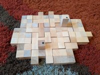
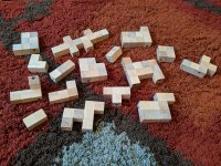
i got a dogpile game a while ago, but it's hard to stack the little plastic dog pieces. so i got some wooden inch cubes and put them together with glue and screws. and made a few of my own shapes. i like how they turned out...
IMG_20190724_194555.jpg IMG_20190724_194447.jpg
 
Another struggle while making PCBs using "McGyver" method. This time no need to improvise etching agent from contents of kitchen :).
I decided to make a replica of Pong-like game, to be exact the earliest design I will find in domestic magazines. I have found a nice one in 1976 magazine, made of 7400 chips, resistors, capacitors, NPN signal transistors, diodes, a single 7474 2-flipflop chip and some counters to divide frequency to get TV picture.
Because PCBs were quite like technical drawings, with tracks represented as thin lines, I decided to put schematics and PCBs (7 5x10cm boards) to KiCAD and redraw them, with ground filling and similar "bells and whistles". I simultaneously started to collect parts (over my basement) and I think I have all of them.
So I found that I will have to use the "crisis" method of making PCBs at home too as with new toner in my printer, thermal transfer is still not an option. It just does not come from the paper!
I have cut and cleaned the laminate, printed mirrored (relatively to these mirrored used with toner transfer) layouts, sticked one to another and started to mark holes. The result was nice. OK, let's paint.
Problem 1: The marker. No, I don't have any thick enough to cover copper against B327 (sodium persulfate), So, let's make one. I found an old syringe with a needle. Carefully cut the needle (not to close it) leaving about 1cm, put a thin wire inside, wound it in spring in the end inside syringe and poured a bit lacquer there. This idea is quite well known and allows to paint with some paints, the wire is pressed and it leaves some of lacquer, after releasing it comes back moving in the needle back and forth.
Problem 2: The only suitable lacquer I found is an old nail polish. Best before: 2004. It does not go through the hole! Even when there is no wire.
So I found another makeshift solution: Removed the syringe's piston entirely, inserted an end of a tube (cat. 5 cable shield) there, the other end of tube to the "bulb"-like blower to put a pressure in there.
Problem 3: It is possible to paint tracks well, but after contents of bulb is exhausted it is needed to suck the air in. This agitates the lacquer and the bubbles are left in it, decreasing precision.
Solution: Removed the bulb entirely, installed a longer tube, one end to the syringe, the other end... you guess. I have never played any wind instruments, but now I know that it must be hard. The most important thing: Blow, do not suck. I literally "blown" 3 boards. Advantage: Track thickness is regulated by how much I blow and it's so precise that I can decrease track width while leading track between DIP holes just by blowing. Disadvantage: Constant blowing into tube for an hour is exhausting.
So finally, 3 boards are ready: Power supply unit, sync pulses generator and "ball" generator. It generates a white square on the screen and I can move it, now by temporarily installed variable resistors.
And these PCBs... actually they're not so bad. They don't look as good as these from good thermal transfer, but do not look as bad as these when thermal transfer goes bad. There are no "holes" in tracks. There is a good separation between them, I think even better than with toner transfer as edges are more sharp.

I will finally get rid of these transistors I have, with TO92 housings, with labels like "08 33" or "13 56" I have no idea what are they for, but they work well as signal transistors.
 
  • Like
Reactions: rSl
Not sure if this fits in the "project" category exactly, but given the limited free time I have, it's about as far as I'm able to go for the time being...

I finally rid myself of the only proprietary software I was still using - Simplify3D. It is very good slicing software, and I was a little anxious as it was also the *only* slicing software that I had used. However, stupid DRM finally prevented me from using it, and I am now using Cura... couple of crashes here and there, but apart from that I'm finding it much simpler and intuitive to use. Kind of wish I'd tried it years ago now.

I do need now to re-calibrate my printer though - feel that the bed isn't low enough, and the first layer isn't as tight as it should be.

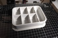
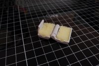
Anyway, here are a couple of the latest prints I've made (both from Thingiverse): a small parts tray (which includes notches where you can scrape off magnetized screws), and a filament dust filter (someone also suggested adding a drop of oil although I'm not too sure about that). It always impresses me that things like hinges can be printed, and also immediately work perfectly.

Actually the 3D printing itch has well and truly caught me again. I'd lapsed for a couple of years, but now I'm browsing for more stuff to print...

printer_1.jpg printer_2.jpg
 
Tree House : The Avocado Mayhem finally being released! :)
Congratulations.

I have a few criticisms of your video.
It feels all backwards... Starting with the chaotic things going down them wrapping up their picnic blanket. I presume this was intentional, but I didn't have a clue what the game was about for at least half of the video.
Also your cuts feel like the video is glitching/jumping, which I suppose it is, but it's a bit jarring. I think this is because the background is fairly consistent, but the players just jump from one place to another. Feels like you could do with crossing effects between clips - whether it's fading one to another, or a white/black covering flash. Alternatively, making a special demo mode in the game engine to play everything you wanted to conceive in the video in order would help show everything off in one take without cuts
 
Yes everything intentional. It is a single screen game so there is not much to show, fun comes from certain in-game situations hard to cut in pieces.
The game itself has an intro story I didn´t want to reproduce on the teaser not to be redundant, hence the rewind.
Game also starts slow and picks up, I didn´t want the trailer to start slow otherwise people might sleep.
But yeah, lots of people see it like glitch, same for the burger lord trailer. :D
Maybe it is just a bit too much "bomb the bass"?

Certainly doing a single shot with scheduled in-game stuff like you said would be best, I didn´t think of that.
I will add another video which has pure gameplay-only when steam is ready to go.
Thanks!
 
It feels all backwards... Starting with the chaotic things going down them wrapping up their picnic blanket.
I liked it. It starts with the action, so it's shows it's not boring for the first 5 seconds and captures the attention then, when the awesomeness dulls a bit I was like: Too hard for me... and then the easy level is shown. And I was like: I can do that!
 
Back
Top