Share your projects


I´m a bit worried about the difficult level, the bosses are very hard and it is tough to balance
I once made them easier just to get an 8 year´s old getting to the second boss on the first play, so I made them harder but it gets discouraging if no one gets there in a whole day of gaming. I get very different responses from all groups of players I tested to this day.
I hope the current balance is fine.
 
Certainly doing a single shot with scheduled in-game stuff like you said would be best, I didn´t think of that.
I will add another video which has pure gameplay-only when steam is ready to go.
Thanks!
Do keep the reverse difficulty, as you're happy with it, and @FBnil seems to like it too. I think just getting rid of the cuts would make it look much better.
Or one alternative idea: Start with the very start of the game - they open the blanket, and catch a single avacado, then hit your reverse difficulty curve. Just gives you 5 seconds to understand the concept before the screen goes chaotic.

I presume when you say gameplay-only, you're still going to leave you title card in there?

I´m a bit worried about the difficult level, the bosses are very hard and it is tough to balance
I once made them easier just to get an 8 year´s old getting to the second boss on the first play, so I made them harder but it gets discouraging if no one gets there in a whole day of gaming. I get very different responses from all groups of players I tested to this day.
I hope the current balance is fine.
Could you have easy/hard mode?
 
I get very different responses from all groups of players
It just means your game has a wide appeal; from casual gamers, to very good gamers. Why not, as pmprog suggests, add a second "easy" mode, but if you die on a bosslevel, just for that session, the boss gets easier (for example, does 20% less damage), with a minimum threshold of easiness, until the boss is beaten? Other ways to make it easier: drop an item with 10 seconds of invincibility when on the brink of death; give extra points to people that do NOT use it.
 
Yep, the gameplay video should have the title, but I might as well skip the game intro there as it is a bit long. Easy and hard mode is a bit difficult here because of the game type I guess. The power ups were originally thought to be the easy mode since if you collect them, they make the game very easy and the boss fights slightly easier, let them crash if one wants a higher challenge. The drop item for invincibility is also a great idea to help this front.
Also, each power up that materializes, if not collected(crash), you gain 5 point to a total of 20 (4 power ups). This is a score based game, it has many endings for different scores, I don´t think anyone will ever beat 2 of those endings but the idea is that they help push the player into another game just in case he can do better and get to the next one, an inexperienced player spends 1-2 minutes for a game, an addicted person might reach 4minutes but the full game run happens between 5 and 7 minutes, so it is quick to try again.

Thanks a lot for the feedback, I should have been sharing the project while ongoing because there is good solutions mentioned.

The game was originally conceived for the caanoo, I later adapted to android and pc, it should also be pandora friendly.
By the time it reaches STEAM, I will try to find some time to work on ports.
 
Thanks a lot for the feedback, I should have been sharing the project while ongoing because there is good solutions mentioned.
There are pros and cons to doing that; whilst you can get some good ideas, it can also introduce a lot of feature creep, which can really mangle your project.

I can still only dream of getting to your position with something to release ;-)
 
Yep, I know a bit of the feature creep. The Burger lord game has plenty of those turned off inside the code, the good part is that it didn´t take too long to discard them.

edit: added a gameplay video. Should add a making of this week hopefully.
 
Last edited:
Another Pong problem or the non-filtering of interferences.
So last time I finished making PCBs and power supply unit. It was quite hard to make a generator, especially as it starts from 1MHz with my poor PCB technology but finally I got it. All readings on scope were OK, TV started to react to signals and take its blue screen out, so I decided to build a ball board.
The board worked from the first time. I connected voltage inputs to pots and moved ball on screen. After fitting proper capacitors (trial and error), ball started to have the same width as height.
Similarly everything went OK with paddles - they were and, after putting a few more trimmers around main potentiometers, they started to appear where they should. After messing with capacitors they even got the same dimensions. Doesn't matter that I calculated ca. 4.5-4.7nF on both and got best results with 3nF on the left and 3.3nF on the right :).
When I switched TV from 5" to 10" one, I found a problem: There were interferences on vertical sync. Picture slightly waving up and down. This would look terrible on a large screen, so I started to trace it.
In this design, vertical sync pulses are taken from mains transformer, it is regulated with Zener and then goes to flipflop. After flipflop it's negated and a pulse is stretched with RC. There was no problem in this circuit - when I disconnected mains transformer input and fed 50Hz from generator interferences went away. But as voltages from transformer reached Zener diode, everything started to wave.
So I decided to minimize interferences by placing capacitor after flipflop. I quickly found that this gives no effect and I should look for culprit around NAND which sums sync signals to composite. The "waving" effect would be then caused by sync having interferences on composite, but NOT having them when it goes to e.g. drive ball/paddle generators.
So the first thought: Take the vertical sync signal which goes to mixing, capacitor, ground. And I got the strangest possible effect: Everything works perfectly until I go about one meter away from the device - waving comes back. Because target enclosure will be made mostly of metal, I think that the "effective good-operating range" will decrease :). So, not this way.
After insulating and making sensitive tracks not running in parallel, after trying to filter out different interferences with different capacitors with no effect, I finally decided to do something totally opposite: Do not filter the interferences out, but make the device run with consistent interferences in all signals. So HSync going to mixer, 33pF capacitor output of Zener diode.
Works perfectly.

Another problem: These transistors. They behave... strange. I took them from some old printer driver with CM-class CPU, with power supply made using germanium technology. I understand that there are two silicon NPN transistors with the same markings in the same packages having totally different pinouts, but they were probably made for switching applications only. Their voltage characteristics vary so much that I had to replace them a few times as they had too narrow amplification characteristics.
 
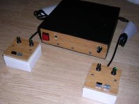
Finally the "Pong"-like is ready.Most parts are salvaged from different things, generally the design uses late 1970 - early 80s technology. Relatively simple from outside.
001.jpg

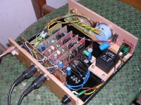
Inside, there is a power supply unit, a set of modules, and all controls:
005.jpg

I have a quick description of modules too.
 
@PCXT That is simply awesome! Good layout too, so clean (the layout, not the soldering). I like the touches, like having a fusebox outside the box. Or the big condensator for the mode (or is that the reset?) selector. You are using the wood as a resonance box for the speaker.
I guess now all it seems to miss is a fancy '70-ties logo?
 
In my mind at least, the fancy logos basically came in slowly from about '77 and hit maintream in about 1981. Properly late 60s/70s in terms of computing is a homemade wooden box to enclose your electronics, so I approve of this mightily.
 
@FBnil
The switch is mode selector, the mode works by extending one paddle in height. The paddles are generated just by stretching pulses, so adding more capacity = longer/wider paddle.
The wood, or rather floor panel material (a bit more sound absorbing), was the problem as the "speaker" is the phone handset speaker so it was not audible from the inside at all. I finally found the solution:
1. Speaker right to the panel.
2. The dome-shaped empty space cut in panel in front of the speaker.
3. A set of holes drilled (finishing with a flat drill!) from the dome as close to the surface as possible.

About this green thread on wires... It seems to be the only way to keep the wires in such devices in order if no ribbon cables are used.

The PCB soldering is a mess. The solder not only holds the components in place and supports components added later (plus fills too large holes, as first boards I drilled with a needle), but also fills "holes" etched accidentally in PCB, especially in ground floods. Generally a whole PCB fabrication in my conditions is quite problematic (this was painted from a print-out and etched), as when I made schematics in KiCAD from the article, I found some errors in connections both in schematics, PCB, and in design itself (one subcircuit was doubled). Almost no component value in the design was proper and components had to be fine-tuned by changing them. One of the errors present in original design was interesting, as pulse width for calculations was taken exactly 5 times bigger than it should be. If you look at most old oscilloscope's zoom buttons it is obvious how this got into design :), The need to fine-tune values is the reason why some capacitors and resistors have "additional passenger" in serial or parallel.
Also, an interesting part is the overridden current limiter in voltage regulator. Originally someone specified the current which would be right if proper 7400 chips would be used. This has been even tested with western 7400s. But these old 7400s from the era and from this manufacturer tend to take bigger current than in datasheet and I always got over by about 100-200mA. This plant also made ROMs which could "swallow" even 200mA in normal operation.
The connectors are totally wrong ones. Originally I was planning to use 1970s connectors with 5mm raster, but during assembly I found that my connectors have no straight angle, so I had to improvise with typical gold pins. Good thing: it stays in place and holds well. Bad thing: It not only looks bad, but some pins had to be bent and soldered in this form.
 
Last edited:
3. A set of holes drilled (finishing with a flat drill!) from the dome as close to the surface as possible.
ROFL :D so cool! So the holes are not visible from the outside, but they are there!

additional passenger
I've seen that on many old electronics. last minute fixes to not throw away the board. (like bridging IC pins with a resistor)

but some pins had to be bent and soldered in this form
Oh, so the box would not survive a ride in a car? (would require re-soldering parts that came loose)?

especially in ground floods
So that's a plus working with wood: It makes a bad conductor and saves you from electrocution. /Joke

That being said, I can't even make a led light shine without it dying because I did not use a resistor.

Just a question more about that center-right-low black octopus thing, is that there to dissipate heat?
 
I've seen that on many old electronics. last minute fixes to not throw away the board. (like bridging IC pins with a resistor)
Sometimes they were right in a design, just added in some specific versions, like for FM ranges in export versions of radios. Sometimes they were added in "starting" stage, when the mchine was started for the first time after assembly and inspection. I remember seeing a Z80-based computer with literally tens of capacitors soldered into IC pins, And... the second unit I saw had of course capacitors in different places as ICs manufacturers were slightly different. That's why the manufacturer, which made typewriter previously, almost went bankrupt with these machines.

Oh, so the box would not survive a ride in a car? (would require re-soldering parts that came loose)?

This will certainly survive vibrations. The thing is that the pins have been installed without soldering bending them as needed, then removed and properly bent to deform and then soldered in. This is especially visible in paddle modules, in which pins coming into board are slightly bent outwards starting from this plastic "casing".

Just a question more about that center-right-low black octopus thing, is that there to dissipate heat?
Yes, this is a heatsink. These heatsinks were commonly used not only with transistors, but also with some ICs in TO3 casings.
I tend to do two things too much in these devices: Giving too big power reserve in transformer and giving too big capacitance on the output of power supply unit.
 
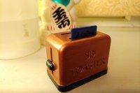
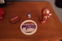
Just varnish it if you feel it needs it I reckon. I do like the look of that SD toaster, but am disappointed I can't use the slider to mount and unmount them.

Yeah, that would have been cool. What triggers my OCD more is that the design has the slider in the "down" position, yet SD cards sit in the "up" position in it. I still like it though.
 
Back
Top