More from Galaksija "replica" log:
(first part:
Here).
2018-11-11
Initial assembly started. Lots and lots of jumper wires, I haven't soldered them all. Going from right to left, jumper wires first, then IC sockets. After I soldered copper wire as jumpers in ZX97Lite clone and it darkened, I decided to use insulated wire with nice green insulation where possible. So, under sockets it's impossible, and under keys too, copper wires from network cable go there.
These nice Tesla green sockets won't fit as it's not too much space between ROM/RAM sockets. I used one in character ROM.
There are more problems than I initially thought. I see that tracks are porous, it's hard to stick solder to them and if it sticks, it sticks to the PCB too. Soldered ROM/RAM sockets, it's hard. The only method to finally stick the socket's pin to track was to install socket, bend pins outwards or inwards as much as possible, brush it with flux and use capillary forces to pull the solder: Heat the pin, push the alloy under it.
Some tracks have visible holes, some have visible links. Before starting it will be needed to clean the situation with an ohmmeter, soldering iron and knife. Tomorrow: CPU region.
2018-11-18
Assembled keys, sockets, jumpers and most resistors and capacitors. There are significant problems with tracks, lots of fixing as they are "porous", so ordinary coating with alloy does not fix the problem. The keys used are a bit different than original, so I had to modify holes and it's impossible to correct their orientation as it was with original computer using a separate plate. It generally looks nicer now, no shorts on RAM/EPROMs, character ROM not tested.
2018-11-20
Assembled everything. Removed more shorted/opened tracks. Startup -> No clock. Removed problem with too big cap in generator circuit, restored broken connection between inverters, clock ran, there even is something like a sync, but nothing more. Found that D0 is shorted with clock and corrected it. Still no result.
No reaction to reset. There are errors on official schematic, especially related to pin numbers on glue logic. Russian schematic (Fifan's) is better, the only mistake seems to be related to data lines on 74LS174 in which two of them are flipped, but on the other side of chip they are flipped too. Additionally something seems to be wrong with resistors for video, so I'll take video from between resistors of a modulator divider. It looks like the machine bursts all components on the same logic levels, so everything goes messy.
2018-11-22
OK, there are probably more bad connections, let's roll heavy cannons now. No boot up and CPU does some babbling on buses, activating RAMs and EPROMs. I decided to buzz through all connections using Russian schematic as a reference. Found that two chips just have no power and quite important connection to move video out is broken. Fixed and tried to boot.
Partial success - there is a READY prompt, but the computer seems not to work stable way - CPU hangs, memory writes are going not where intended, and picture lines are missing, LISTing simple program returns gibberish. Because the clock is derived from a single oscillator, I decided to diagnose the following way:
1. Change CPU. This computer seems to work well with a "80A MME" East German CPU... and no other. Even original Zilog's Z80 and clone with "R" in logo break timings and it crashes before displaying second picture line (ROMs stop to be readable too early).
2. Mess with capacitors. This was a good idea. I had no other 5nF, so hacked 4n7 using soldering iron

. CPU seems to run stable now, but picture is still missing random lines and... it looks like it warms up, after 20-30 seconds it's OK.
3. Mess with generator. Good that I have an oscilloscope.
Now the most important thing to fix this issue: Without oscilloscope, Initiating this computer is just trial and error. Timings are critical, one gate flips too fast (still in datasheet tolerances) and data goes to the wrong place. I have bought a new inverter chip for clock generator as I knew that this is a generator, parasitic capacitances in dirty connections from unsoldered 30 year old chip may kick in, gates have to be fast, don't they? Well, here NOT. The clock for pixel generation just has to be delayed specific amount of time or it will make italics. I finally found a set of logic that works with minimum capacitors added and there is this 30 year old 74LS04. Additionally, my new CD4040 (manufactured 2010) used as clock divider seems to mess timings too (firing interrupts too fast) and I had to use an old Harris chip to make it go properly.
The computer successfully executed a simple arithmetic program for 15 minutes and did not hang! Draws about 0.66A of 5V, so it can be fed using 78L05 regulator.
Summing up: Now I have to find a cheap casing for it.
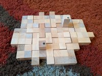
I got the mainboard laminate from my friend who was working in laminate factory years ago, I also have A4 samples of other laminates, not copper-coated. Maybe I'll make a frame of flat wooden boards, in which the front panel made of laminate sits on junctions in angles, and the mainboard just slides in? Something like this.


