Case Sneak Peek


I doubt ED would be "bothered" by well-thought out ideas as he's an adult who can either embrace them or skip them as he's always done. Imagine if the naysayers had their day, as they almost did, with both pairs of shoulder buttons(there's no room, it's too late in production to modify them, can't place them at the corners), but time, research, and some chosen Nintendo DS ifixit.com pics did permit changes from those "rice grain" triggers we almost got.  ;)
We still don't know how good the new triggers will work in practice but let's hope for the best. And I'm 99% sure they are at least the better solution than these first "rice grain" trigger ideas. :D I'm personaly still prefer the new Nintendo 3DS solution (same as the NeoGeo X ) but we know there is just no space for.
Yeah, there's no room for side by side L1 L2 triggers a la the 3DS on the Pyra, but something that always nagged me about it all was why the micro hdmi wasn't simply stacked directly above the headphone port like the micro USB debug port above the USB 2.0 port was to fit triggers horizontally?

What I'm getting at is how often would a person use the HDMI Out to a much larger display concurrently with headphones plugged into the handheld device(here I'm assuming both cannot be plugged in at the same instance)? Wouldn't they typically use the full sound from the external monitor or, if they absolutely must have bedroom silence and a large screen, plug in their earbuds to the outer display's audio out port? I'm not concerned about it anymore but it was a past curiosity, and maybe a sensitive question better left unasked for some, why Nikolaus didn't try it. :)   
 
Last edited by a moderator:
Most probably because there's space on the other side of the PCB where the USB port is, but not where the headset port is.
 
so... you want to connect a 2M long earphone lead into a TV 4M away instead of plug it into the device in your hands (which is the actual source....) ?
 
Most probably because there's space on the other side of the PCB where the USB port is, but not where the headset port is.
Seems about right. Speaker bays and perhaps the rumble look to reside there. Oh well.   B)
 
Last edited by a moderator:
I need more news about the Pyra in my life. It's strange to think I've been following the Pandoras development and now Pyras development since 2008 back when I was debating to get a GPH handheld.
 
I need more news about the Pyra in my life. It's strange to think I've been following the Pandoras development and now Pyras development since 2008 back when I was debating to get a GPH handheld.
I wouldn't mind some new news as well.  Of course, I understand if ED has been too busy with development as of late, since things are coming together quite fast.  I think they were going to get a full test unit assembled soon; hopefully when they get to that point they will show it off! 

-Glyph Reader
 
What I'm getting at is how often would a person use the HDMI Out to a much larger display concurrently with headphones plugged into the handheld device(here I'm assuming both cannot be plugged in at the same instance)? Wouldn't they typically use the full sound from the external monitor or, if they absolutely must have bedroom silence and a large screen, plug in their earbuds to the outer display's audio out port?
My only HDMI sink currently is a monitor, hooked up via an HDMI->DVI adaptor that doesn't split out the audio, so if I used that I'd be plugging bigger speakers in at the same time as getting the video over HDMI.
I'm in a similar situation, I have a DLP projector and while It does have a tiny speaker in it, I need to use another source of sound output on all my devices to bring it to my surround sound system. 
 
Last edited by a moderator:
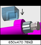
The bezel part of the new designed Pyra lid (not visible in the sketch) has an notched piece that will slide over the bolt and additionaly holds everything in place when the lid is fully assembled. Imagine the transparent piece is part of the bezel (the black screen cover inside the lid as seen here in ED's sketch
post-1-0-73353800-1424023774_thumb.png
) :


Also not visible, the bolt is held in place to the right side within the case of course. The "spring-stop" simply collides with an stop inside the case part so it can only pulled out to the left when the lid is opened. ^^
That's quite a neat idea. I was a little confused by the blob covering the end of the hinge axis that's part of the bezel piece until I understood that it's not doing anything to the axis - it's there to stop the lid hinge part (coloured darker in your images) from sliding into the lid under the action of the spring.

I see that spring being problematic though. It's in danger of making assembly quite tricky - I'm envisaging it'll be a little different to the Pandora in that you'll align the lid back with the base, then slide the hinge assembly in, then clip in the bezel. That spring's going to be trying to force the hinge back out before you've got the bezel in. I suppose it's there to keep the base part of the hinge (lighter coloured) in contact with the lid piece, and provide resistance as the lid locks in position and is forced out.


I wonder now which sides of the bezel are clipped, and which are screwed. It might be easier to concentrate on locking the lid hinge piece in place as you insert the bezel if you didn't have to worry about aligning some clips at the same time.
 
That's quite a neat idea. I was a little confused by the blob covering the end of the hinge axis that's part of the bezel piece until I understood that it's not doing anything to the axis - it's there to stop the lid hinge part (coloured darker in your images) from sliding into the lid under the action of the spring.
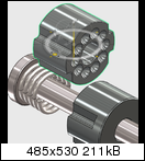
In theory, the bezel piece could be just flush to the bolt and no axis is sticking out anymore, but I made this more complex design basicly for two reasons: first, it's easier to pull out the hinge piece and second, the axis is longer and can spread the forces a little bit more, in that case also to the screen cover piece. I imagine it is more rigid that way compard to an shorter axis. And the bolt axis can have a little bit of tolerance in there because the actual hinge locks are held in place seperately. (That's the advantage in opposite to the screw-held design where the lenght of the axis must be very precise and must contain a threaded part .)
I see that spring being problematic though. It's in danger of making assembly quite tricky - I'm envisaging it'll be a little different to the Pandora in that you'll align the lid back with the base, then slide the hinge assembly in, then clip in the bezel. That spring's going to be trying to force the hinge back out before you've got the bezel in. I suppose it's there to keep the base part of the hinge (lighter coloured) in contact with the lid piece, and provide resistance as the lid locks in position and is forced out.
Yupp, you are right. The spring tends to push both lock bolts backwards. I imagine it may be a short, tight spring that only works towards the right side and does not push back alot when the mechainsm is in "relaxed" (open) position. However, I also have an solution for this. :D As long as the spring does not push back the cylinders that far, a slight curved shape of the bezel part could help to "auto-push" the entire hinge in the right position.
 

I wonder now which sides of the bezel are clipped, and which are screwed. It might be easier to concentrate on locking the lid hinge piece in place as you insert the bezel if you didn't have to worry about aligning some clips at the same time.
The new screen cover bezel ED mentioned could support this mechaism, because ED sayed it is only screwed at the right so it must slide in to the left side first and then closed to the right before fixed.  I know that a simple nut (first design) may be the more elegant solution because it will hold the mechaism independent of the LCD cover piece. 
 
The other benefit to a bolt/nut solution may be in manufacturing. The place that produces the plastic parts can assemble them on the bolt and tighten the nut and send the hinge as a coherent unit. Although if they're using a lock nut and overcompress the spring, that could be a pain (although looking it up, nyloc nuts are apparently reusable, so adjusting one shouldn't cause a failure).


I still find the idea of a nut-free solution appealing for some reason. Although again, perhaps an unsecured spring (with the case disassembled) isn't the best hacker-proof idea ever. Boing!
 
Yes, since I included these "stoppers" to the hinge-lock piece, it should be always in the perfect position, no matter how tight you screw in the nut. This way the hinge lock piece is always flush with the gap between lid and main case. You still need a (bezel) piece that presses the entire mechaism to the right but it can be more simple and only has to push against the nut, which doesn't change in lenght at all. :) The only thing that changes when you screw thighter, is the force of the spring.

Oh, I also had another additional idea, the loose lock piece that is pushed has no "stoppers" because it has to slide of ocurse. This way it can be used both sides and you can have 2 different patterns of lock-notches on each side. The first still has the 3-lock positions and the other side has more, like a ratchet or so. All you have to do is disassemble the mechanism and turn the lock piece 180°. How is that? :D


(Yes, I switched positions of the positive/negative lock pieces for that reason. The "positive" domes are now in the fixed lid part.)
 
Last edited by a moderator:
I think having the bezel interact with the nut is likely to be awkward. The nut can be in any orientation when it's first inserted. If it's possible to get a nut small enough that there's enough free space around the nut for the bezel to interact with the lid lock piece it might work better.

Having more options is always better. I actually wonder if this will provide enough resistance, suitably tightened and sprung, that a useful setting might not have any lock positions, and works like a laptop hinge. I guess that could be left to the user to take out the hinge lock piece and sand off the humps if they want though.


Oh, and I'd add a washer between the spring and the case lock piece, to stop the end of the spring digging a groove into the face of that piece that you might want to use later.
 
I think having the bezel interact with the nut is likely to be awkward. The nut can be in any orientation when it's first inserted. If it's possible to get a nut small enough that there's enough free space around the nut for the bezel to interact with the lid lock piece it might work better.
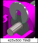
Well even with nut at the left end, you need somethign to prevent the entire mechanism to just slide out left. ;) I desinged it so that you slide the mechanism in from the left through the hole in the lid and then through the base case where it is also stopped in the right distance. You then need something to stop the entire mechanism to fall out left, it has no fixing clips like the old Pandora hinge has. And this stopper part must be onto the bezel because you need free space in the bottom lid to slide in/out the entire mechanism. ^^"It just has to push from the left against the nut, nothing that really "interacts".


Again, this is a part of the (not visible) bezel and can be actualy also smaller to prevent to much friction. It just has to hold everything in place when the lid is assembled.
 
Last edited by a moderator:
Hmm, have you checked the availability of such nuts? The sort of lock nut I'm thinking of is hexagonal in extrusion and need the axis to pass through it and out the other side because that's where the thread locking nylon is.


While the plastic parts can be specially produced, I'd have thought you'd be better off with a design where the metal parts can be sourced from multiple suppliers. Although we're already talking very skinny threads - I'm not sure if a M1 screw is small enough. Can you take measurements from your design?
 
I had to ask the wiki about lock nuts because I didn't knew how these work. I'm sure we could live with a (single end) normal nut, just tightend enough. Lock Nuts like you describe seems to be not re-usable but this design is supposed to be reassembled. And it is meant to be simple. ;)

measurements are basicly around the actual Pandora barrel hinge piece. A little bit longer beacuse of the nut but overall the same size because I made the profile out of the existing hinge and it's holes in the actual case. The diameter of the bolt and it's matching nut may vary, can be wider, whatever is available and fits, same for the spring area.

The diameter of the lock bolts is ~6mm, each one is 4mm long (may vary in practise). Overall lenght in this "sketch" is currently ~16mm, including nut. Diameter of the main bolt is 2mm but I would prefer something thicker actualy.

By the way, I would like to see na opened NDS barrel hinge, how these are actualy working. Didn't found anything yet in the net. I'm really no "hinge expert", I made this design straight out of my mind. :D
 
Last edited by a moderator:
I'm pretty sure you need a lock nut. Look up nyloc nuts, those should be reusable enough for our purposes. According to wikipedia there are loads of other types of locknut, but the only ones I am familiar with are nyloc nuts and doubled nuts.


Since the parts of the hinge are meant to spin relative to each other, every time the lid piece moves counter clockwise the nut will tend to follow it and unscrew itself. Then, when the lid piece moves back, clockwise, the nut is unlikely to tighten itself up again since the spring is working to push the nut against the threads (it would have the tighten itself uphill, so to speak). Over time it will loosen.


If the bolt is long enough, once the nut loses contact with the hinge piece it will stop spinning because of it. If the hinge piece is held in place some other way by the bezel that won't be a problem, but if you're relying on the nut at all to hold everything in place, it'll need to be absolutely firm, else the hinge assembly will tend to slide inwards towards the lid while the hinge segments are aligned, and thus lock the hinge in position at best, else cause the hinge segment which is half-way through the junction to fail drastically due to torque, or even cause the external hinge to fracture as the grooves in that are torn apart by the rotating hinge piece.


There's no value in looking at patented designs except to discover whether the idea you've settled on is already patented.
 
Hm, the nut actualy turns with the bolt freely, independent of the lock pieces. The only contact would be against the lid-lock piece. This would need alot of friction to unscrew such a tight nut.

Well, the chance may be small but still there. Non-nut design may not work because of the forces of the spring, I guess they must be compared strong to work efficient (and after looking at the existing bolt hinges). So my alternative design may be out.

OK, no nut, and no nut free solution too, hmm...

How about a groove in the bolt plus an metal "clip" piece that is also been held then by a bezel support piece to prevent it to slide out?

 
Last edited by a moderator:
As I understand your design, the nut can't be that tight, as it's not tightened against a fixed object - if it's tightened so that the spring compresses, the hinge parts won't move out of their locked positions.


Your clip solution I've seen before. They're workable, but a bit of a pain to get on and off - perhaps difficult in assembly, and definitely tricky in hackability (since we want people to be able to disassemble the hinge so they can swap the parts about).
 
If the clip part was like this (Forgive bad artistry x­D)

clip.png

It would only have to slide into the groove and rotated couterclockwise and then could be held by the bezel.

Then you wouldn't have to worry about it coming loose, and there would be no trouble taking it out because of tight clipping.
 
Back
Top