You are using an out of date browser. It may not display this or other websites correctly.
You should upgrade or use an alternative browser.
You should upgrade or use an alternative browser.
Should I have received my final order eMail already?
- Thread starter EvilDragon
- Start date
No, not in your case. The charging chip did not report a temperature fault.Don't you think that all the issues may be due to a faulty battery temperature sensor or protection circuit?
If you want to try an 18650 you'll also need a 10k resistor from ground to the middle pin, or a 10k thermistor attached to the battery and connected the same. Most 18650s can take at least 10A
Have you tried just pushing the battery against the contacts! You probabably just need to stick some card or velcro on the back of the battery to push it against the contacts.
Post automatically merged:
Have you tried just pushing the battery against the contacts! You probabably just need to stick some card or velcro on the back of the battery to push it against the contacts.
Last edited:
Yes, I even checked for the proper contacts alignment.Have you tried just pushing the battery against the contacts! You probabably just need to stick some card or velcro on the back of the battery to push it against the contacts.
Well, yes. But we know that the charging chip software "is not there yet" at the moment, so it could be possible that the charging chip does not like something and does not tell us about it at the same time. Thermal parameters could be ok, but also there could be some glitch in the battery protection circuit. Anyway, it is an easy experiment. I always run debugging from easy tests to the complicated ones.No, not in your case. The charging chip did not report a temperature fault.
I love fireworks!I hope you verify beforehand, that that 18650 of yours can handle the current the Pyra may throw at it. ?
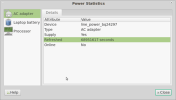
What do you think about this one attached hereto? By the way, as I managed to boot and have a full battery I've ran same tests and scripts you suggested earlier. To my eye nothing changed, so the reason why it now has severe booting problems remains a mystery.No, not in your case. The charging chip did not report a temperature fault.
Status update: 18650 is being prepared, gas mask is on me, fire extinguisher is in my pocket. Funny stuff aside - i didn't manage to make this thing reliably boot. Even battery cooling method does work only sometimes. Trying different flash images and different SD cards didn't help...
Attachments
The huge number for refreshed means no charger has been plugged in yet.What do you think about this one attached hereto?
We bypassed the software by reading the fault registers directly from the chip. They'd be all zeros or random numbers if the bq24297 chip had completely failed.But we know that the charging chip software "is not there yet"
I think we're getting to the stage of this being a motherboard hardware fault (or you've got a great collection of broken micro usb 2.0 cables and chargers.) I think your options are to ask @EvilDragon to examine the motherboard. If you want to take the risk yourself, you can start following the VBUS track on sheet 8 and 13 of the schematics.
On sheet 13: If the serial console is working on the middle micro-usb 2.0 port then we know the USB power gets to the FT232RQ USB to Serial chip. A fault in the OTG circuit (U1205 and U1207) would stop the power getting from the USB to the charging chip (BQ24297 on sheet 8).
I like ED too much and appreciate his work on making a user serviceable open source device. Thus I won't disappoint him and send back a motherboard with no blown capacitors and burned tracksI think your options are to ask @EvilDragon to examine the motherboard. If you want to take the risk yourself, you can start following the VBUS track on sheet 8 and 13 of the schematics.
Well, I am still alive while Pyra is running of a new batteryIf you want to try an 18650 you'll also need a 10k resistor from ground to the middle pin, or a 10k thermistor attached to the battery and connected the same. Most 18650s can take at least 10A
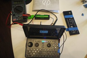
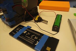
No good news apart that though... No charging, same boot issues. I've added a battery killswitch to this 18650 setup to ease testing. Now we know:
1) boot issue is not affected by the battery temperature or the battery "brain" and sensors;
2) it is likely to boot when power was disconnected for a prolonged period of time - so we are in fact waiting for some capacitor(s) to discharge;
3) these issues are not related to the battery;
4) most likely motherboard is faulty.
Attachments
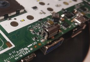
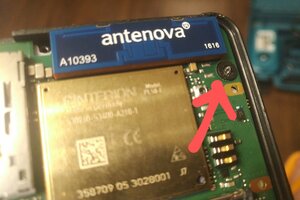
Oh, I've got inside this thing... We won't be checking the circuits. Just see the photos I made.A fault in the OTG circuit (U1205 and U1207) would stop the power getting from the USB to the charging chip (BQ24297 on sheet 8).
Also, I am definitely unlucky. The last screw holding the case together was sitting in a messed up thread. Had to drill it's head away to open the case (the result is on the third picture). So I will most likely need a new top part of the case as the geometry will not let me cut new thread and use the next size screw.
Attachments
Last edited:
levi
Still fresh, damnit!
I had the trouble of my Pandora that I was unable to remove any of the deep screws using hand tools; I think the paint on the case was so thick in places that it wedged the screw heads in their channels. After rounding out the head using hand tools the remaining shape made it quite easy to center a drill the head, so I used a small bit to drill out the length of the screw leaving a ribbon like thread which I pulled out, and from the other side it was relatively easy to poke the remains of the heads out.
Well, that's definitely an option. The problem with this particular screw is that it is a hardened one, so drill slips from its core destroying the plastic "barrel" in which screw sits. I still can cut the whole thing with the stuck screw, drill a trough hole and squeeze the two parts of the case with a bolt and nutI had the trouble of my Pandora that I was unable to remove any of the deep screws using hand tools; I think the paint on the case was so thick in places that it wedged the screw heads in their channels. After rounding out the head using hand tools the remaining shape made it quite easy to center a drill the head, so I used a small bit to drill out the length of the screw leaving a ribbon like thread which I pulled out, and from the other side it was relatively easy to poke the remains of the heads out.
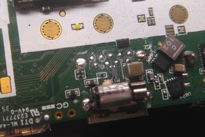
Your first photos of the solder joints for the blue USB port: what do you think the white smudges are? I guess solder paste, or water marks? On my board, one of those joints looks cold soldered (rough texture) but it has made a contact.

levi
Still fresh, damnit!
Probably crystals from dried flux. Not uncommon on commercially manufactured boards that require a little hand soldering to affix big or otherwise difficult parts to the board.
Last edited:
I've spent some time with a magnifying glass and a toothpick looking at it (sometimes i regret having shitty camera in my phone with no macro lens). Basing on my experience it looks like a heavy corrosion provoked by flux which was not washed off - it is flaky and peels off, while metal underneath looks corroded and circuit lacquer is damaged. But on some parts it is a bit different – on vibromotor balance it is very thin and covers only one side, very similar to a result of nearby capacitor explosion (I’ve checked the nearby capacitors – visually they look ok). Some spots have dark color, which could be flux burnt during soldering, or a short circuit due to the said corrosion.Your first photos of the solder joints for the blue USB port: what do you think the white smudges are? I guess solder paste, or water marks? On my board, one of those joints looks cold soldered (rough texture) but it has made a contact.
I was thinking about washing it with some isopropyl alcohol to expose the damage and testing the device after that. But at this stage my soldering skills are far inferior to what could be needed to be done, especially bearing in mind that it is a multilayer PCB. Thus I think it is time to reach ED and check his recommendations. I think he won’t need this PCB back as it is most likely damaged beyond repair, so he might give me green light for more intrusive experiments – if I manage to restore it we are good, if not I will get a replacement.
Ok folks, I've just talked to ED  He is a great guy, some people here really shall appreciate him more
Bad news - we are not messing with Pyra internals any more, as ED wants the PCB back for further investigation of what could have gone wrong. Good news - I will clean it, inpect and test. If it won't get back to life - I will get a new motherboard under warranty.
Bad news - we are not messing with Pyra internals any more, as ED wants the PCB back for further investigation of what could have gone wrong. Good news - I will clean it, inpect and test. If it won't get back to life - I will get a new motherboard under warranty.
At least this should help improve the Board Produktion, as you only can improve when you know the bugs,
At least you can Change the Board by yourself, which is a big advance from the Pandora/Pyra over other Mobile Devices..
I would suspect this new M1 Imac want be that easy fixable as the Pyra..
At least you can Change the Board by yourself, which is a big advance from the Pandora/Pyra over other Mobile Devices..
I would suspect this new M1 Imac want be that easy fixable as the Pyra..
NetBLOKS
Finally on-board
I really appreciate the work the early adopters are putting in their devices.
Analyzing the problem and testing everything out instead of crying about a damaged device is what makes the product better for all of us!
Keep it up!
I am really looking forward to my own pyra!
Analyzing the problem and testing everything out instead of crying about a damaged device is what makes the product better for all of us!
Keep it up!
I am really looking forward to my own pyra!
MrConfusion
Very Active Member
- Joined
- Apr 11, 2013
- Messages
- 331
Second image, that chip next to the text U605: is that a solderbridge between the first two pins (uppermost in picture)?Oh, I've got inside this thing... We won't be checking the circuits. Just see the photos I made.
Also, I am definitely unlucky. The last screw holding the case together was sitting in a messed up thread. Had to drill it's head away to open the case (the result is on the third picture). So I will most likely need a new top part of the case as the geometry will not let me cut new thread and use the next size screw.
Similar threads
- Replies
- 3
- Views
- 7K
- Replies
- 218
- Views
- 99K


