I wish you could feel things through the internet!


this picture is a close up, more high res pyra pron is welcome :happy:
Make that a 20 minute long 4K ASMR video, pretty please. I need to hear more of those sweet shoulder buttons clicking.
I'm a needy greedy fire-breathing bastard, but I guess... A normal, standard Pyra video would suffice as well :p
 
this picture is a close up, more high res pyra pron is welcome :happy:

I assume that's in a test jig of some sort, because I see no sign of the shoulder buttons yet that's the top of the board we're viewing, and the microHDMI port looks quite a long way from the hole (but then maybe it's an old photo and the positioning wasn't adjusted by then).
 
I assume that's in a test jig of some sort, because I see no sign of the shoulder buttons yet that's the top of the board we're viewing, and the microHDMI port looks quite a long way from the hole (but then maybe it's an old photo and the positioning wasn't adjusted by then).

Test jig? It's sitting in a Pyra clear case turned upside down. The bottom piece is removed.

The shoulder buttons are there - top right of the photo. The shoulder button key caps connect into the base plastics that are removed for that picture.
 
Yes, I can see the switches - I was referring to the keycaps when I said buttons. Maybe that's a pyra case lid, but that seemed unlikely at the time given the LCD cable is connected - but maybe he just wanted to mock it up quickly I guess.
 
Yes, I can see the switches - I was referring to the keycaps when I said buttons. Maybe that's a pyra case lid, but that seemed unlikely at the time given the LCD cable is connected - but maybe he just wanted to mock it up quickly I guess.
Not the lid - though the lid is likely behind it. The plastics there would be the keyboard surround/hinge piece. It is resting on what is/would be the screen/lid. That LCD cable looks like a mock-up and may actually be 'connected' to an actual screen behind/under what we see in the picture.
 
It could be pretty hard getting these through the hinge - and the second problem is that they're probably too wide to fit between the MicroHDMI port and the shoulder buttons.

See that picture here:

View attachment 30281

While the connector is wide, the traces themselves don't have a lot of space there.
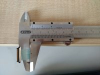
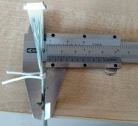
No, it wouldn't be hard. See these pictures.

IMG_20170420_135214.jpg IMG_20170420_135508.jpg

The wire thickness is 0.25mm, only slightly more than of the flex tape.
The wires bunched together have 2mm diameter. That's 3,14mm2 field of section. The hole between the PCB and the case is about 5,5x1,3mm = 7,15mm2, judging from the adjacent uHDMI connector. Two times more room than required :)

The thing is that the wires behave like a flex cable when you want them to fit through a narrow slot, but can be bunched together when you need them to go through a round hole. This eliminates the twisting of tape, and no more hard edges scratch one against another.

The connector on the pictures is 30-wire. I don't know how many you need, but with that cable you wouldn't need any redundant wiring, so I guess 20 would suffice. That would make the thing require even less space. Also you wouldn't need any ground connections, as each of the wire is coaxial - ground signal around the data signal, so you get 20 ground connections without using up any signal wire.
 
Well how much do those cabels cost compared to the Pyra once? And are they easy to source in Europe or do they need to be ordered from China? The Pyra is being developed on a limited budget and if a new design LCD cable that is both cheaper and more reliable compared to similar designs can be produced then that will probable be the choice, I think EDs solution is a smart one. And a huge selling point (at least for me) is that most parts of the system are made in European countries with more fair labor laws then compared to companies like Foxcon in China.
 
The thing is that the wires behave like a flex cable when you want them to fit through a narrow slot, but can be bunched together when you need them to go through a round hole. This eliminates the twisting of tape, and no more hard edges scratch one against another.
Not quite accurate. I am very familiar with stranded ribbon cables. They have their uses - and this isn't one of them. This little cable deserves it's engineering. Consider what it is expected to do.
1. Connect to a very low profile connector on the system board without transferring any torque to it..
2. Turn 90* inside of a few mm.
3. Run through a 2mm diameter barrel around 5 mm long.
4. Turn 90* inside of a few mm again.
5. Connect to a very low profile connector on the display board without transferring any torque to it.
6. Twist 170* on it's axis between the two 90* turns (#2 and #4) tens of thousands of times without breaking OR resulting in torque to the board connectors.

Your example cables flex in ONE direction, along the flat, poorly. They do not handle short radius turns well. They do not handle repeated mechanical movement on short radius turns hardly at all.

Yes, you can curl it up along the length to make it into a pencil shape so it can go through a hole. BUT - you cannot do that AND bend it over and over in a hinge while it's bent into a pencil shape.

So, that type of cable is NOT appropriate to send through a mechanical hinge pin. There IS a way to use it, but that would require a substantial redesign of the case plastics. IBM Thinkpads use those multistrand flat ribbon cables to connect the screen. They simply go flat through slots in the base & lid that have high clearances - sloppy fit, but a good thing in that case. They use your example type of cable, but they certainly don't stuff it through a hinge then bend it 90* on both sides of the hinge then mechanically twist it 170* over and over.
 
Last edited by a moderator:
IBM Thinkpads use those multistrand flat ribbon cables to connect the screen.
Maybe the older ones do, I know for sure that the T4x and T60 series simply use reinforced foil cables, ribbon cables are only being used for the backlight due to its low pin count requirement.
 
Maybe the older ones do, I know for sure that the T4x and T60 series simply use reinforced foil cables, ribbon cables are only being used for the backlight due to its low pin count requirement.

T60. Note the gigantic flat cable connecting the base to the screen just left of center. You don't normally notice it looking down at the machine on your desk.
s-l400.jpg

T400 lid & screen from a previous message above.
aI5XBaUg.jpg

Slightly bigger photo; still can't see anything. Derp.
 
Note the gigantic flat cable connecting the base to the screen just left of center.
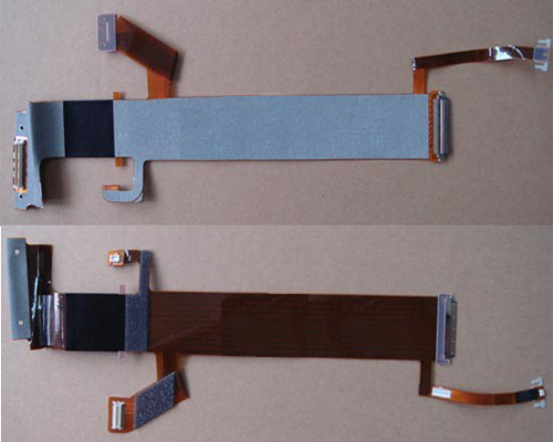
It's a plastic covered foil cable, if I had a cam at hand I could open up my T60p for you. Here's some random replacement part picture of the whole T60 cable:

s506875824555543720_p285_i1_w500.jpeg


The short part to the left connects to the motherboard, it is being fixed by a small metal plate with a rather sharp edge that tends to damage the cable if you're not careful during disassembly.
 
Last edited:
It's a plastic covered foil cable, if I had a cam at hand I could open up my T60p for you. Here's some random replacement part picture of the whole T60 cable:

The short part to the left connects to the motherboard, it is being fixed by a small metal plate with a rather sharp edge that tends to damage the cable if you're not careful during disassembly.

Cool - I learned something new.
 
Back
Top