EXT connectors


No EXT connectors going out tonight. I forgot I volunteered to help run some charity billiards tournament thing and I'm not going to get out of there until after the post office closes. The job comes with free food though. :D
 
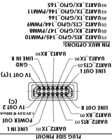
So this diagram shows the pinout from the "plug side" what does that mean?


cable_connector.png


Is this the view when looking at the front of the EXT connector or the back?


The connector is also upside-down (judging by shape) on the Pandora compared to the above diagram.


In other words when I plug the connector into the Pandora like in WizardStan's [Huge] photo here:

IMG_20110518_182413.jpg


What is the top left pin in that picture? Line Out L or TV OUT 1 (Y)?


Thanks!!!
 
Pin 1 should be on upper right, if You are looking straight on Pandora's rear side:


Code:
 _____________

/ . . . . . 1 \

| . . . . . . |

|_____________|

Now, check BoB schematic :)


B, b, b, But wait! On schematic is pin 1 dedicated to Audio R out...
 
Last edited by a moderator:
Pin 1 should be on upper right, if You are looking straight on Pandora's rear side:


Code:
 _____________

/ . . . . . 1 \

| . . . . . . |

|_____________|

Now, check BoB schematic :)


B, b, b, But wait! On schematic is pin 1 dedicated to Audio R out...

I think I will need to do some tests before soldering any permanent connectors... or use one up for testing... I do have a bit coming to me to play with.
 
I suppose MWeston could sort this for us pretty quick.


In the mean time I think this is what the plug is like when facing you.


flipped_cable_connector_pinout.png


Which would suggest that when plugged into the Pandora like in WizardStan's picture the top left pin would be Line Out L.


Just thinking out loud, I stand correctable.


Paging MWeston. . .
 
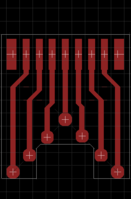
I'll type already here - sorry for duplicity, but I think that not everybody read TV-out thread. So, I'm going to let manufacture circa one thousand tiny PCB for soldering directly into connector and allowing easy soldering wires to it. It should be something like this but in better quallity:tinybob.png (grid raster is 1 mm) For better pricing it could be printed in 10 x 10 pcs on one plate and then separated by plate shears (or sold altogether).


If You like it - feel free to send PM me with suggestion. I'll can't promise applying any suggestion I'll get, but I'll use it as clue and will think about it. This tiny size fits into USB A housing that I can order for circa $0.6 - $0.7 and bundle with tiny BoB if somebody wish.
 
Last edited by a moderator:
I'll type already here - sorry for duplicity, but I think that not everybody read TV-out thread. So, I'm going to let manufacture circa one thousand tiny PCB for soldering directly into connector and allowing easy soldering wires to it. It should be something like this but in better quallity:View attachment 575 (grid raster is 1 mm) For better pricing it could be printed in 10 x 10 pcs on one plate and then separated by plate shears (or sold altogether).


If You like it - feel free to send PM me with suggestion. I'll can't promise applying any suggestion I'll get, but I'll use it as clue and will think about it. This tiny size fits into USB A housing that I can order for circa $0.6 - $0.7 and bundle with tiny BoB if somebody wish.

What is bob? Also, I would buy 10 of these boards and housings, are you aware that the spacing between the two rows of pins is less than the thickness of a typical PCB?
 
Last edited by a moderator:
Also, I called TycoElectronics because their drawings had a note about contacting them if you intend to connect to a PCB, expecting an email reply by Tuesday.
 
What is bob? Also, I would buy 10 of these boards and housings, are you aware that the spacing between the two rows of pins is less than the thickness of a typical PCB?
BoB - Break out Board.


And space between connectors rows is 1.2 mm (by drawing) which is enough. I even see 1 mm thick PCB (double sided).
I just wanted to be sure you were aware of the space limitation, I did know that you could get PCB thinner than standard (used to mount CPU on)(I don't know why I'm so strongly compelled to clarify this, oh well, here it is.


Also, the attached image was enough to model it in sketchup with good accuracy except for some minor details, I can has the source file?


Finally, do you want input/help designing the through hole PCB?
 
So this diagram shows the pinout from the "plug side" what does that mean?
It means exactly that. You are either a plug or a receptacle. The Pandora has the receptacle. If you held a plug up to your face, it would look like the picture I made.

Is this the view when looking at the front of the EXT connector or the back?
The front since it is clearly not a pins view.

The connector is also upside-down (judging by shape) on the Pandora compared to the above diagram.
Yes, connectors are on the bottom side of the PCB so they are upside down in the case. The SD cards being the exception because reversed parts are readily available.

Pin 1 should be on upper right, if You are looking straight on Pandora's rear side:


Code:
 _____________

/ . . . . . 1 \

| . . . . . . |

|_____________|

Now, check BoB schematic :)


B, b, b, But wait! On schematic is pin 1 dedicated to Audio R out...
I wasn't really paying too much attention to what was pin 1 on that schematic when I made the parts since it was such a simple project. The pin 1 in that schematic is really just referring to my ribbon cable's pin one on its socket.

And space between connectors rows is 1.2 mm (by drawing) which is enough. I even see 1 mm thick PCB (double sided).
It looks like I used 1mm boards. Any bigger and it won't fit easily due to the plated copper pads making the whole thing thicker.
 
I just wanted to be sure you were aware of the space limitation, I did know that you could get PCB thinner than standard (used to mount CPU on)(I don't know why I'm so strongly compelled to clarify this, oh well, here it is.
:) That's totally OK - we say "measure twice cut ones".
Also, the attached image was enough to model it in sketchup with good accuracy except for some minor details, I can has the source file?
Yes, but... OK, I'm not familiar with any CAD SW, so I ask and other boy does it. Attached picture is first draft modified in MSPaint :-|
Finally, do you want input/help designing the through hole PCB?
I definitely think that trough hole PCB will be better, but could it be done in such small form PCB? But yes, if You are willing then I gladly accept You help B-)

It means exactly that. You are either a plug or a receptacle. The Pandora has the receptacle. If you held a plug up to your face, it would look like the picture I made.
...


The front since it is clearly not a pins view.


...


Yes, connectors are on the bottom side of the PCB so they are upside down in the case. The SD cards being the exception because reversed parts are readily available.


...


I wasn't really paying too much attention to what was pin 1 on that schematic when I made the parts since it was such a simple project. The pin 1 in that schematic is really just referring to my ribbon cable's pin one on its socket.


...


It looks like I used 1mm boards. Any bigger and it won't fit easily due to the plated copper pads making the whole thing thicker.
Thak You for clarificatin!
 
Mine turned up this morning. These things are *small*. I now understand the need for a break out board. Heck!


Having never seen a Pandora in the flesh and having only ever seen the port magnified. I suspect the Pandora is smaller than I've imagined thus far.
 
I definitely think that trough hole PCB will be better, but could it be done in such small form PCB? But yes, if You are willing then I gladly accept You help B-)
I actually think that maybe through hole is not he best way to go, doing this would mean enlarging the PCB significantly and I suspect it may even be HARDER to slolder but I cannot say for certain. (I practiced a bit of soldering to the pads on a 32MB stick of ram).
 
Mine turned up this morning. These things are *small*. I now understand the need for a break out board. Heck!
Take a piece of card (like a cut out from a cereal box) and slip it between the two rows of pins. This'll give some additional support as well ensuring solder doesn't drip between pins. Use a spare ribbon cable (ide hard drive cable from an old computer) and strip the ends. Tin the exposed end, and soldering it to the connector side pin should be a snap.
Oh thank goodness I read that, I hadn't thought to use ribbon cable.
That's exactly what old PCs are good for: a source of cheap (although dusty) ribbon cables. When I start running out of ribbon cables, I know someone in the family is due for an upgrade. ;) (or someone forgot to give me their old PC)
 
Still waiting for mine. I'll probably receive a resealed envelope with a customs sticker on it... :S


I want these babies!!!


oh, this waiting seems so familiar :p


Cheers!
 
Back
Top