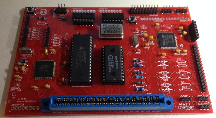
Zikzak - crummiest 8bit console/computer ever .. but I'm making it!


I'm sooooo tempted to get a 3d printer, so I can knock out a case, too, without bothering anyone. I so want to have a little box with a cartridge slot on it :)

I am also tempted to build a SID-emulator into the sucker or another sound chip easier to knock off kits for, and increase RAM too. (Which is very easy, just cost a few bucks to make another pcb.. tempted to, just for lulz though.) With more RAM, could run somethign like Linux on here :p

jeff
 
^Do it!


My 3D printer was one of the best investments I made.. I paid ~650 USD for mine, but it still produces excellent prints despite lacking auto bed leveling and such that newer more expensive ones now come with.
 
Last edited by a moderator:
See, re: 3d printer, its a tough one; on the one hand, just totally goddamned awesome; on the other, hard to justify the price, in the expectation that in a few years the price will comew way down, the machines much faster and more stable and featureful, etc. Also, I worry about the fact none of them can usefully do convex shapes :)

Theres a few cheapo ones now, in the couple hundred range; theres a good pile in the sub-$1000 range, and of course the big boys. Theres a store with Kossel Express' ready to buy down the road, which just pains me.. but can't ifnd any info on it at all; but it sure goes pretty fast, and the demo prints they have are pretty impressive.

One of the points of worry is.. okay, so you have a flat up front cost, that you grin and bear; but the cost for material spools or liquids is pretty pricey, right? Say you want to knock out a box for sometyhing.. its not one unit thick, its oging to be a few mm thick to have any strength at all, and could be lartge.. like a half a foot square cube say .. that'd cost quite a bit in material to print, no? And probably take a few hours/days to do :) Still, you _can_ do it, which is awesome :)

--> torn!

....

I've had so little time, because one of my little guys has started with night terrors and such .. so by the time I get all 3 to bed, an hour later one is waking up again; driving me nuts :) one hopes he settles and I can have a few hours in the post-midnight phase again :eek:

..

Sound was driving me crazy; the bloody AY-3-8913 not working on board. It all sure looks good in the schem and board and pcb, and I had the 8912 working (sort of.. by itself, but fighting with other peripherals, and hence the switch to -8913 which has a real chip-select on it.)

I pulled the sound chip and ploppe dinto breadboard and wire dup an avr8 (my original test setup to prove the audio works as I expect at all, a year ago), and damned thing worked fine, just like the -8912 did back then. I figured this at least proves the chip worked, though the avr8 code and wiring is different to the on pcb (ie: it hard enables the chip select to be live, rather than togglign it at high speed, interleaved with RAM etc.)

So I was thinking of going back to ez80 cpu-base pcb rev1, where it was just the ez80 and support, but no gpu etc, from 6 moago, and jumpering over to the breadboard.. but then I had the even better idea.. since I socketed all the ICs on the current rev board, I could just jumper from the socket into the breadboard. This way I can jumper 1:1 from the board to breadboard, the way it supposed to be, and can also fiddle on the breadboard to alter things. Still no joy. Al the signals look good on logic analyser and o-scope .. no weird electrical crap going on. So purely must just be timing .. I even used a slower crystal on the eZ80, in case the timins for the pulses were too quick (at 20MHz eZ80 they're borderline on the AY-3-891x spec.. so went to 10MHz to double the pulse sizes, just in case.. still no joy.)

In the end, I think the timing on the bus is just too fast/goofy for the thing to handle; theres all that RAM and GPU noise going on .. so chipselect de-activates the audio chip during RAM and so on peripherals, but its still trying to grab the data off the bus. Its a 25 year old chip after all (and eats power like a sonovabitch!)

...

So right now I have spare GPIO B free on the pcb, in case I wanted to drop on some sensors or _whatever_.. use it for any olld thing; GPIO A and GPIO B are for joysticks and serial .. but could also be whatever; but nice to have GPIO B all off by itself, entirely 100% unallocated.

...

Well, I used GPIO B as data to the audio chip, and _Boom_, it works fine.

Goddamned it :)

..

So now maybe I'll make rev3 pcb, with the audio bus over GPIO B instead of the regular data bus; thats a damned shame, but you know, what the hell; I can still leave a jumper to disconnect it (say), or just leave the audio chip off-board if I wanted to do somethign else with it; and since no one will ever use this likely, then I probabyl don't need two joystick ports, so really, it still ahs some GPIOs to play with..

....

So I guess rev3 is in the cards now. *sigh* But maybe _that_ one will be the final finished one :p

jeff
 
Re 3d printer:

I've read quite some from a guy which instead mills molds and casts plastics. The results he showed are pretty impressive and the costs per volume are much lower than when 3d printing.

I wanted to try this, but I'm much too thorough and slow and then I lose motivation when I don't get results, so this is why I don't have any results yet...
 
Re 3d printer:


I've read quite some from a guy which instead mills molds and casts plastics. The results he showed are pretty impressive and the costs per volume are much lower than when 3d printing.


I wanted to try this, but I'm much too thorough and slow and then I lose motivation when I don't get results, so this is why I don't have any results yet...
3D printing is only handy if you are not doing volume work. It's handy for one of projects and quick prototyping. 
 
I've got a couple of people 'around' here which have offered to help out with one-offs, so I may take them up when I get some time; I'm not really on top of any 3D modeling applications or the peculiarities of design (like when you specify a size of 'X' in the gap in the CAD, and them spit it out.. how accurate are the actual processes making the gizmo? With a laser cutter for instance, you have to allow for over or under cut, depending on the actual software and cutter used. I assume a 3d printer has similar issues..) -- consider, if you want to make two separate case halves, and sandwhich them together with slots or latches or something, you want things to marry quite tightly; you can shave off some extra material with an exacto or somethign I iamgine, but can't add extra amterial to tighten.. so how do you design that? (think of a zikzak case that is a bottom half and a top half, say, and a couple cart boxes?

How do the tolerences for (say) self tapping screws work? print a little block, then hand drill a pilot hole and go I suppose..

For a top/bototm case need to consder a lot of factors .. heck, I may need to move stuff around on the pcb to make it  better for that, but ignoring that.. I've got a couple reset buttons in odd places on the pcb; I should move them to be side by side but ugh, its a very complex pcb :) anyway, do you just leave a hole in the case top so you can reach a pencil down and poke it, or do you try to design into the casing a button .. like a little plastic tube, and then a little plastic plug that sits in the tube and rests on the button on the pcb? and if so, how do you keep it from slopping off the button on pcb-side, and from popping out of the case if you tip it over.. wel, you need to make it "+" or "t" shaped, and maybe a spring...

So just considering making a design makes me tired :)

On the upside, with my shitty little windows pro x86 tablet ($230 Dell Venue 8 Pro), which is pretty good actually for what I need (can stream games from my real PC in the basement, for instance, over Steam), it can run the CAD software pretty well, since performance is not a problem for them. bluetooth keyb/mouse combo thing, so I might be able to design while trapped all night in room with little guys, sort of; but bleh. Later :)

So a case is something I'd like to do, but its a whole other side of design .. best ignored for now.

Over the next couple days I'm going to do a slight change to my zikzak zik80 SBV rev 2 pcb, to transform (insert Transformers sound here) into rev3:

rev3:

- Rotate and move a couple headers, to make ISP debugging easier

- dump audio bus over GPIO B to AY-3-8913, so that audio works nicely. Maybe use a jumper to enable/disable or something .. ie: I'm going to keep GPIOB breakout header on the pcb, so can stll use it as GPIO if audio is disabled (either not populated, or even just not used in the current software; can turn the audio chip to high-Z so that GPIOB can work without screwing with it.) -- I do use my boards in my little robotics hacks.. eZ80 'base' pcb rev1  is driving one of my robot cars :)

- RAM upgrade!

  -> I used a AS6C1008 128KB RAM chip - slow at 55ns so its cheap, but plenty fast enough when you're running at 20MHz or less Z80 CPU :) (could upgrade to faster eZ80, but thats not the point of this project)

  -> Theres a 256KB chip (hard to find) and 512KB chip (not too hard to find, and not too pricey at $3 each or so) with almost same pinouts .. I opted for 128KB since it seemed plenty (compare to a C64 etc), and got a deal on the chips; but since I'm revisiting, and I'd designed for this to explicitly allow easy design change.. why not? So I just hook up a not connected pin, and switch some other single wire a bit, and poof .. same pinout more or less, and go to 512KB pcb; can still put in the 256KB or 128KB chips with a quick software change in my firmware, too, so no big loss.

512K hooke dup to 8bit CPU should be pretty crazy .. more space to hold sprites and stuff.

I should update the blog a bit.. www.zikzak.ca is a little out of date, not enough photos and gunk.

jeff
 
Yeah tolerances can be a bit tricky, but once you get a good setup going it can be fairly accurate. I have one odd ball issue with the slicing software (Slic3r) that would mis-calculate inner perimeter of some objects.. I found it was as ~0.7mm to tight.. until that issues was patched, I had to add that .7mm variance into my design.

How do the tolerences for (say) self tapping screws work? print a little block, then hand drill a pilot hole and go I suppose..
You may not even need to drill a pilot hole, just have it in the design.

Some designs of enclosures I've seen around have been pretty good. I'm not sure if I could easily model something that good..

http://www.thingiverse.com/thing:409064
 
Last edited by a moderator:
I've recently updated the schematic and pcb design; I think its all I want to roll into rev3 of the SBC, but we'll see.. will sit on it for a day or two before placing the order in case anything comes to mind.

(I might also design a little atmega BoB dev board, as I use the atmega644 and similar quite a bit for simple little tests, and for robotics etc; such a simple chip, inexpensive, easy to bring up with few components, and available at local stores ... so why not design a little pcb that has the atmega644, ftdi for usb<->serial, space for the crystal, ISP header for debugging, and headers for the 4 sets of GPIOs? Sure, thats similar in the end to a basic arduino, cept it'd only cost me a buck each :)

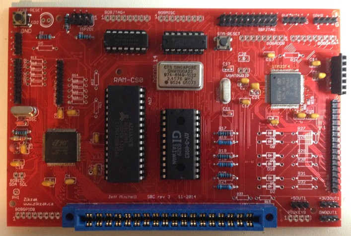
The Zikzak SBC rev3 changes so far:

- rotated eZ80 ISP so easier to program (no more cable twist for me :p )

- same for STM32 GPU ISP header (rotating headers is actually a huge pain on such a tightly routed pcb; there is no free space, and everything is a basketweave .. I am in via hell!)

- eZ80 GPIOB heads over to audio databus, instead of the actual databus to the audio data bus; such a shame, but should fix the audio once and for all

     .. GPIOB still usable as a full GPIO, except those moments in time when the audio chip is having its registers set; if you're not driving audio, its fully open; if you are driving audio, whatever you're doing on GPIOB better know how to ignore that :p (can use chipselect2..)

- RAM options; rev1+2 were 128KB RAM; rev3 is 128KB, or 256KB, or 512KB

     .. added a solder pad to short over A17 to active-always if needed.. may be handy for 128KB SRAM if its being finicky

- added solder pads to hook up GPU PB14/15 as USB port; didn't use full pinheader since not likely to use, but pads are there to solder right onto.. or drill a hole through and stick a pin in

- GPU already as GPIO-A 16bit fully exposed, which features serial and USB and other goods.. but as you can see, I rather like keeping a GPIO fully unassigned in case I want it for something later

- added some labels, etc

Really, its a flexible little pcb, but this is getting nuts; adding USB (via GPU) is sort of cheating, but could be handy.

I'm tempted to port NuttX OS over to it, or even Linux (lol!), so thought it might be nice to have options for USB, even if dumb as shit (through the GPU...); hence the option for 512KB RAM .. you _can_ get linux working in 512KB with a lot of care :) Linux on Z80 would be sick as shit. (Linux on the GPU itself wouldn't be too hard, though it just doesn't have the RAM in it, it has the horsepower.. but as I have the RAM chipselects and full bus going to the gPU, it might be able to fake the RAM with a bit of performance hit.) But its all designed aroudn eZ80 as CPU, so can you imagine..

... a Linux _cartridge_?

That'd have to be a world first :) Linux cartridge for eZ80! ... so nerdy and crazy it might be worth doing.

jeff
 
Tonight I'll assemble zikzak sbc rev3, as defined above; sucks that I had to do another revision, but these 20 year old audio chips aren't liking all this high speed action, so had to switch things up a touch to slow it down for them (blast!)

Can't wait for the sound test tonight or tomorrow, and to verify the new extra RAM works, etc.

Then some basic firmware demos to show off a bit again, and then maybe define the firmware jump table better (a BIOS of sorts), and then start porting NuttX or ucLinux for lulz...

jeff
 
No time to add detail or run real tests for now .. but a quick audio test.. success! So assuming I didn't just break everything else, I think we're in good shape.

Serious (software side, this time) hacking commencing soon!

jeff

edit: Did some quick tests.. so far the RAM works as either 128KB, 256KB or 512KB just fine. The audio is.. working! I need to solder on the cart edge connector and test that I didn't break that somewhere, but I doubt it. Also need to retest the video bus and all that.. but likely all still good, since didn't touch any of that. So I'm pretty confident its all good .. I'm just looking at formalizing some of the very-prototypy-alphaness of the existing code -- add a proper HAL layer to isolate the memory map and such away from applications, make a proper BIOS-like jump table in RAM and a 'standard library' that apps can use to jump to those BIOS routines, and make a nicer boot menu and test suite (the memory test,m keyboard test, video tests, etc). Then its into porting over linux or nuttx for Fancy-OS-on-a-cart, and maybe write up a pacman or space invaders game cart... fun fun fun! More youtube demos to come in a little while.

edit the edit: everything teted works great so far; I've not built new ps/2 keybioard drivers yet, but thats a simple interface and I believe it works; everythig else is tested and woring.. reading the cartridges (and writing them if they're the right kind of eeprom), the bus for cpu<->gpu, audio, joysticks, serial, programming both siudes, i2c, etc etc. I've not tried the new usb interface, but can't see why it wouldnt' work.. its a direct pin on the gpu, but as I never really intended ot use it, its goofy.. just a couple solder pads you can solder onto if needed. Video out is good. Very pleased!
 
Last edited by a moderator:
OKay, so I think this is the 'final' design, unless I decide to make another with actual connectors on it (VGA, joystick, SD, audio jack, power jack, etc) instead of header pins. Everything is working great, and I think it looks awesome too.

zz-sbc-r3-iso-RESIZE86.jpg


zz-sbc-r3-003-RESIZE86.jpg
 
Here is another lame video, but it does showcase a few things. All these lame videos, but they're to prove one specific subsystem or another :)

I'm tempted to work on my mod player or at least a YM/Pokey/AY-3-8910 player, so it can showcase some audio. Maybe I need to order some larger ROM chips and make a big multi-megabytye cartridge, or wire on the SD card support, so I can store music files easier..

https://www.youtube.com/embed/videoseries?list=UUGQF542dq8RhizMRFbBnBaA

That video just shows a simple non-verbose boot (verbose is where it runs the memory test and check various things), and goes right into a textspritemode - text mode with colour/blink/etc just like a DOS terminal, with a sprite-layer overlaid on top. The sprite is full colour, and textmode is colour-per-cell (but of course, the entire video system is codable, changable on the fly even :) So it turns on, waits a sec (I've found this wise, give you a chance to start a device reflash it before it gets busy..), then GPU wakes up and starts rendering (hence the random garbage shows p on display), then the eZ80 wakes up and clears the display, draws some text, and adds sprites.

This is entirely over the bus in real time, no cheating (the GPU is not just rendering everything itself or anyting), so this proves the GPU and CPU are talking via RAM nicely, without any real performance hit. I coudl tune it a bit more as well (its doing a lot of unnecessary memory block copying, and hitting the bus when it doesn't need to etc), but works a treat. Its harder on the system for full raw framebuffer mod.. when the cpu is rendering pixel by pixel to the framebuffer and the GPU is reading the RAM to dump it to display; thats just too much data across the bus at once, so slows everything way down. So full screen 60fps raw framebuffer woudl be hard for it to render, but then.. the retro z80 there isn't supposed to be pumping out full screen raw framebuffers anyway (think back to C64 or SNES etc .. they're using tilemaps, sprites, and changes are around the sprites etc..) .. mind you, you could shove over a fractal routine or something and run it right on the gpu to get crazy performance, so writing scene-demos and such would be crazy on this sucker.

So in the end, its hitting the design goals quite nicely.. retro feel in a lot of ways, yet still has some power if you wanted; its very accessible to hacking (I think anyway :) , and doesn't 'cheat' much (its not using fancy hardware that magicly works.. I bitbang everythign bit by bit, so its more fun/sick). Cartridge slot! Old school sound chip! Limited RAM .. current design rather likes 128KB, 256KB, or 512KB, but coudl be altered to have more. ROM cart can be as large as small as you need really (a few MB no problem.) For some types of eeproms, you can write into them .. so this sucker can flash its cpu, its gpu, or even flash the cartridges right in the slot. Multiple serial ports, i2c bus, some spare GPIOs; it can run an SD card if you hook one up on the GPIOs; you can run a serial-wifi adapter on there, or drive a i2c wifi, or other things; theres even i2c ethernet and so on as well. Expansion is pretty flexibnle.. even aside of all those busses, you coudl make a cartridge that does crazy stuff, since the cart slot has the full bus on it, and 3.3V and 5V power feeds. PS/2 keyboard works, but I've roughed in some pads to solder on usb ports, so its quite conceivable (just have to write drivers up) to talk to USB devices.

With the RAM and ROM combo, it _could_ be made to run Linux. (some sicko just ported uclinux to run on a 68000 with lesser specs :)

*proud*

jeff
 
You know, its funny.. a year ago, it was like this:

Several complete architecture changes and rediculourly large breadboards, to learning a CAD and getting a few board revisions to something asesome. Hell of a year, and givne I have almost no free time.. crazy :)

zikzak3-gpu-memswitch-complete.JPG
 
Last edited by a moderator:
The GPU has enough performance to spit out high res images.. just not the SRAM enough to hold them. (And reading them live off the external ram chews up so much time the actual CPU gets limited processing timeslices.)

The GPU actually has (in this board) 192KB of useful SRAM; I coudl use the slightly more expensive chip and get 256KB sRAM (another bank of 64KB), but that doesn't help too much.

So with the current chip..

SRAM1 (the default RAM) is 112KB

+ SRAM2 16KB

+ CCM SRAM 64KB very fast

I'm currently just being brute force, with 256x192 8bpp colour or 49KB per buffer, and double buffering (98KB total out of the 112KB base ram.)

Doing 640x480 in 8bpp means about 300KB per buffer (ouch), which is why I don't currently do that. (have done, with tricks, of course.)

One option (especially for pure text mode) is 640x480 1bpp (monochrome, be it black/white or amber or green/black or whatever) which is only 38KB

... so at monochrome, it could really drive 800x600 or more pretty handily, including monochrome sprites, and still double buffer

But thats not too fun; on the Atari ST which I cut my teeth on, we had 3 modes.. 320x200 colour, 640x200 limited colour, and mono 640x400. So you see my influence in this regard :)

Another option is 640x480 4bpp (16 colours per pixel out of palette, which is what the ST had at 320x200) .. that would chew up about 150KB; more than the 112, but could split it into a couple banks and make it work. or 640x400 4bpp which is an even 2*64KB, single buffer (some limited tearing.)

I've envisioned a few graphics modes.. from pure textmode, to text+sprite like the last video, to big sprites no text; and different forms of compression; and of course raw framebuffer where cpu can draw per pixel.

Guess I should add text high res mono double buffer for the word processing and console shell I'll never write*, and 640x400*4bpp high res limited colour mode for games I won't write :)

jeff

*well, I do plan on building a BASIC, and who knows, maybe port over NuttX or Linux.. so maybe a high res text mode will be useful.. (for varying definitions of useful)
 
Last edited by a moderator:
This thing looks like fun:) I've always liked 8 bit computers but have never been lucky enough to find one in the wild to play with.


They're a bit before my time
 
Last edited by a moderator:
Oh, it definately is fun ;)

Sorry quick spam here, in a rush

I'm not sure how to proceed, if others want; as is, with a requirement for audio to be a PSG, it seems impractical to 'mass produce'; dropping an avr8 on there to simualtre a SID could make all the components readily available (well,  the eeprom chip I use in my cart is getting hard, but I might ake a prototype board for cart, so you coudl solder whatever you wanted on there...) .. so not too hard.

But with current design, a few could be done; theres the two 100pin surface mount parts which are a little tricky to solder (took me a few tries before I got good at it, and now its no problem.) (I highly suggest having a USB microscope for inspection though!) .. the rest is all throgh hole and easy pleasey.

So if your'e good with soldering, I coudl be talked into sending myou a bag of parts; if your'e not good at soldering, it'd take me setting it all up and testing it for you; which could be done, but not somethign I want to do a lot of.

I didn't add up parts cost, but say $60-$80 is the total cost of a populated board.

Software wise.. right now I use dedicated programmer units to flash things; I coudl write some software (need to do anyway) for the unit, so any old ASCII/USB could program the cart (and then have the cart program the rest of it, maybe..) .. so software work for me.

.. so if anyone wants it, it right now depends on their skills and interest; its not yet bundled up in a ready to use way for someone who just wants to fiddle with a finished and easy to program unit.

It is tempting to pollish it all off, so peopel could just flash carts and make games/apps, and not worry about the main board.. but I've not spent much time making fancy end-user oriented firmwares yet; its all been test-firmwares to prove each component bit by bit, for myself

jeff
 
Back
Top