Working well so far, though a little dumb bad luck at the wrong moment ..
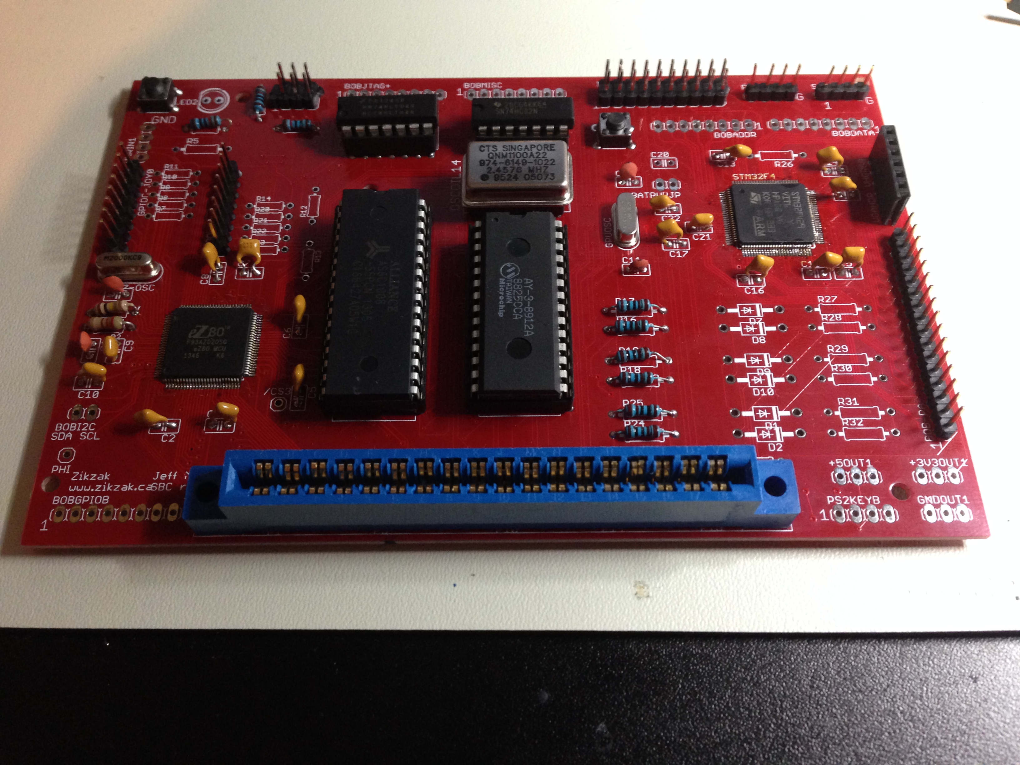
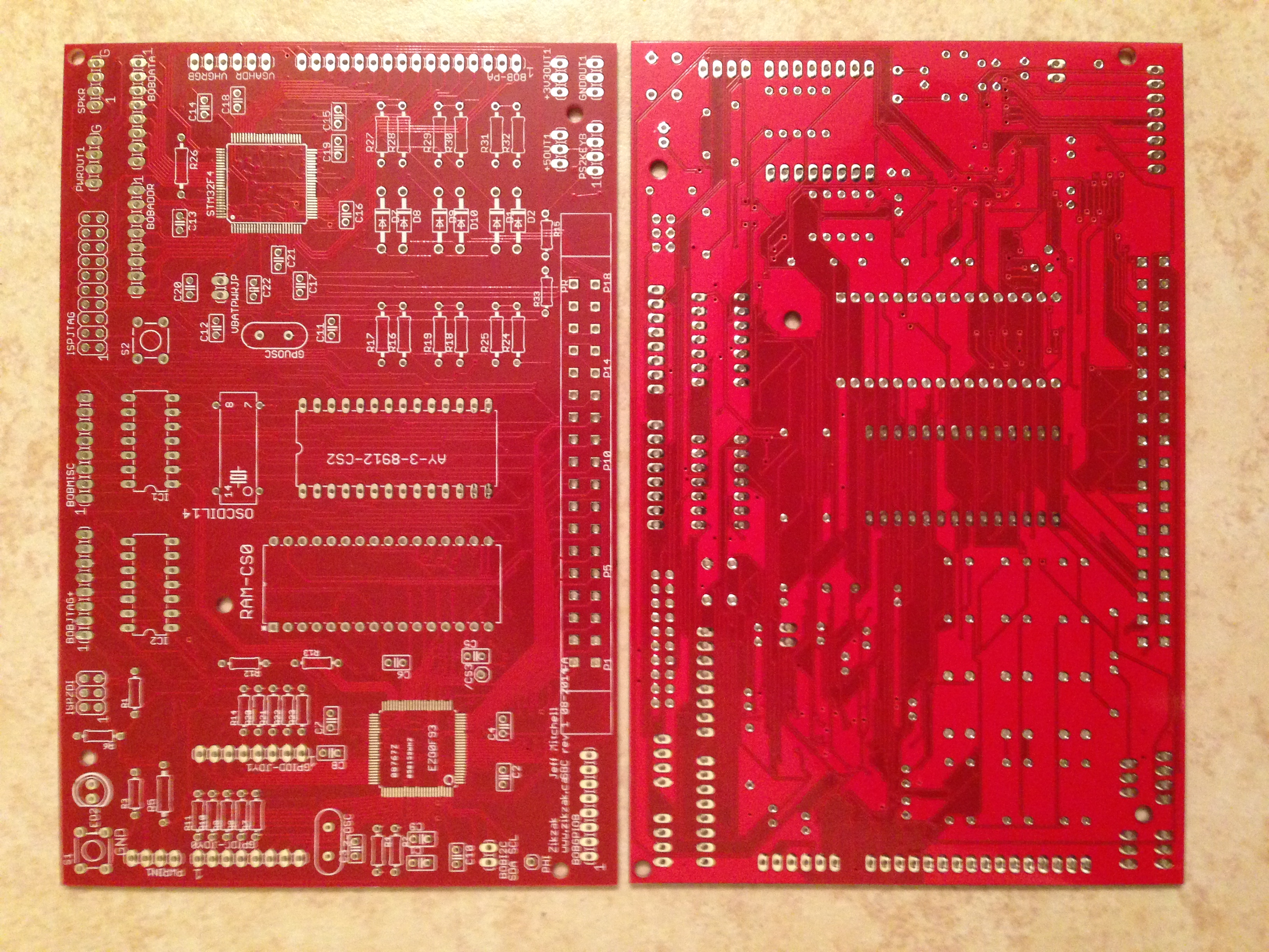
First, check out these sexy pictures; I think this is a hot looking board. Good size too .. little longer than a pop can is tall. (6"x4") .. expensive little bastard though! (4"-square is about $12 for 10; this guy was what, $38 for 5; factor in another $20-ish for shipping, and we're talking roughly $60/5 or $13ea, compared to about $3ea including shipping for the little guys.)
Mostly populated, from an angle top down view:
And a shot of the top and bottom unpopulated pcb:
What works so far?
- the GPU (stm32) rendering to VGA works a treat! did two revs of the dedicated gpu board, so I should hope so!) (so flashing it, running, clocking it, etc)
- the CPU (eZ80) running .. perfect (again, programming it, clock, etc, all good.)
- GPU -> serial -> USB -> console, to send commands to the GPU works fine
- Audio (driven by CPU) works great; means the OR and AND gates and oscilator all good (think about it.. got a 20MHz clock for eZ80, a 16MHz oe 8MHz clock for STM32, and a giant case oscilator for the Pokey AY-3-89xx)
- reset switches, etc, all that stuff okay
This suggests almost certainly that joysticks, keyboard, are okay.
Pretty certain cartridge is okay, but will test that later.
What I screwed up:
- so far, nothing wrong in the design!
But when soldering it all together (which takes quite awhile actually, since I'm pretty careful or slow) .. a couple pads on the STM32 side lifted off the pcb, and the pins got bent a bit while I tried to address that; sadly, on pins I need. (the stm32 pins are only half used, since I'm keeping it more or less a dedicated GPU, and not relying on it for fancy stuff. Now, you can surely use the STM32 as the cpu and have it control the bus, driving games entirely from the high speed ARM chip

.. but I've not really wired up a lot of the extra pins.. a spare GPIO for sensors/etc, and all the bus stuff, and the VGA stuff, and thats about it. The GPIO includes the serial parts of course, so thats still available.)
The pads that got funky look like the A14 and A15 sort of area; I'm fairly sure they're not shorted together or into something, as a continuity check is not turning up anything obvious. I think they're just left floating right now.
The result (of something, hoping its 'just' that loose pads) is that when the GPU hits the bus to read from the CPU, its getting garbled image back; its definately grabbing the bus BUSREQ and getting the BUSACK response, and its definately eeing the RAM more or less okay (can see whats going on), but its getting 4 copies of the image tiled.. like, a 2x2 grid of the image, and all garbly. You can see the image the Z80 is presenting, but its mlutipled and garbled.
It could be something else though.. and debugging this will suck. Going through all those solder joints, and checking the hardware design, and all that, will be a lot of guesswork and probing. But hey..
.. nearly there

Its mostly working, and the design still looks solid and awesome; audio is playing! I need to write up the keyboard driver for the z80 (currently avr8 based) and get that tested, and test some gpios and joysticks and the ROM cartridge slot .. but really expecting fully working there.
So, once I debug the likely bad solder between these two guys, it'll be time to write some basic demos and games to show off

jeff


