Following up the last blogpost where I posted that the battery contacts needed to be realigned, we now received the test PCB with properly placed battery connectors.
1. The optimized battery connection
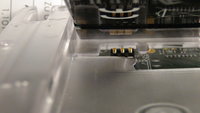
You can see on this picture that they now are properly aligned to the contact pads on the battery:

Of course, how it looks like is not important, important is that it is being tested!
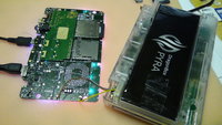
So here is Nikolaus test setup:

The test PCB in inside the case, including the battery. And the battery connectors are directly attached to a real working Pyra PCB.
Nikolaus can then test the contacts by checking what the charger chip reports and whether the battery loses contact.
And guess what: It's rock solid!
Charging, discharging is now working properly, no wrong readings anymore!
Nikolaus tried wiggling around the battery as much as he could, but the contact never failed or lost contact.
That's how it's supposed to be!
But on the same test PCB is something else... and that's...
2. The new hole-through MicroUSB-OTG port
While sourcing parts for the Pyra a long time ago, we only found a surface-mount MicroUSB-OTG port.
However, sometime during development, a new hole-through-port has been released - which we just bought and tested on the test PCB.
The port works exactly the same as the old one - however, thanks to the hole-through pins, it's rock solid and you will not be able to break the Micro USB port!
Before you break the port, it's more likely that the cable or even the PCB breaks...
Anyone who ever owned an N900 will surely appreciate that.
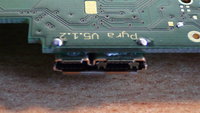
Here's a picture. Doesn't that look solid?

With these two final tests we made, the mainboard can now be finalized and go into production for the prototype run as well!
Now ALL PCBs are finished - and if everything turns out fine, no more revisions or changes are neeeded.
3. The LCD-Cable testing PCB
As reported a while ago, the LCD Cable had some improper connections because I thought the ears were too close to the port?
Well, it turned out that was okay - the cables actually work.
The reason the prototype boards here had connection issues with the LCD cable was something different:
Back in July or August (can't remember the exact date), we received samples of LCD Cables where the stiffener was a bit too thick.
Because of that, it was really hard inserting the cables into the mainboard - but not impossible.
And for GamesCom, these were the only cables we had - so we used them to assemble all the units.
After GamesCom, we received the update cables with proper stiffener - but those didn't work properly, so my first idea were the ears.
But it wasn't! Actually, an original 3M cable (not custom made) we were using with the EVMs also stopped working.
And the one in my unit also stopped working after I unplugged and replugged it a few times.
So... the too-thick stiffener killed the LCD Cable connector!
This is good - because it means we most probably don't need to change the LCD Cable design - which means they would be ready for mass production now!
The connectors on the mainboards will be reworked (no big deal).
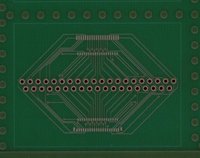
However, we want to be sure everything is fine, so we designed this little PCB:

It's not populated yet (will happen tomorrow), but basically, it's a cable loop.
On the PCB, there will be both types of connectors (the one that's on the displayboard and the one that's on the mainboard) and each connection has a test point.
With that, we can simply plug in the LCD Cable, and test each connection with a multimeter so we can be sure both the cable and connectors work fine and don't lose contact easily.
Of course, I'll let you know the results of the LCD Cable test. But if it works fine (as we suspect), we could easily get all the needed LCD cables for the mass production during December.
That's it for today! Moving along with those small tweaks, but I'm happy they work out so well.
1. The optimized battery connection
You can see on this picture that they now are properly aligned to the contact pads on the battery:

Of course, how it looks like is not important, important is that it is being tested!
So here is Nikolaus test setup:

The test PCB in inside the case, including the battery. And the battery connectors are directly attached to a real working Pyra PCB.
Nikolaus can then test the contacts by checking what the charger chip reports and whether the battery loses contact.
And guess what: It's rock solid!
Charging, discharging is now working properly, no wrong readings anymore!
Nikolaus tried wiggling around the battery as much as he could, but the contact never failed or lost contact.
That's how it's supposed to be!
But on the same test PCB is something else... and that's...
2. The new hole-through MicroUSB-OTG port
While sourcing parts for the Pyra a long time ago, we only found a surface-mount MicroUSB-OTG port.
However, sometime during development, a new hole-through-port has been released - which we just bought and tested on the test PCB.
The port works exactly the same as the old one - however, thanks to the hole-through pins, it's rock solid and you will not be able to break the Micro USB port!
Before you break the port, it's more likely that the cable or even the PCB breaks...
Anyone who ever owned an N900 will surely appreciate that.
Here's a picture. Doesn't that look solid?

With these two final tests we made, the mainboard can now be finalized and go into production for the prototype run as well!
Now ALL PCBs are finished - and if everything turns out fine, no more revisions or changes are neeeded.
3. The LCD-Cable testing PCB
As reported a while ago, the LCD Cable had some improper connections because I thought the ears were too close to the port?
Well, it turned out that was okay - the cables actually work.
The reason the prototype boards here had connection issues with the LCD cable was something different:
Back in July or August (can't remember the exact date), we received samples of LCD Cables where the stiffener was a bit too thick.
Because of that, it was really hard inserting the cables into the mainboard - but not impossible.
And for GamesCom, these were the only cables we had - so we used them to assemble all the units.
After GamesCom, we received the update cables with proper stiffener - but those didn't work properly, so my first idea were the ears.
But it wasn't! Actually, an original 3M cable (not custom made) we were using with the EVMs also stopped working.
And the one in my unit also stopped working after I unplugged and replugged it a few times.
So... the too-thick stiffener killed the LCD Cable connector!
This is good - because it means we most probably don't need to change the LCD Cable design - which means they would be ready for mass production now!
The connectors on the mainboards will be reworked (no big deal).
However, we want to be sure everything is fine, so we designed this little PCB:

It's not populated yet (will happen tomorrow), but basically, it's a cable loop.
On the PCB, there will be both types of connectors (the one that's on the displayboard and the one that's on the mainboard) and each connection has a test point.
With that, we can simply plug in the LCD Cable, and test each connection with a multimeter so we can be sure both the cable and connectors work fine and don't lose contact easily.
Of course, I'll let you know the results of the LCD Cable test. But if it works fine (as we suspect), we could easily get all the needed LCD cables for the mass production during December.
That's it for today! Moving along with those small tweaks, but I'm happy they work out so well.

