Just preordered Pyra and Pandora questions


No idea about the copper circle. Never had my USB-A socket off, so I've never seen it, but I guess that if it's connected to anything it's connected to GND.

I suppose I should clarify that when I was talking about shorts getting hot, that only applies to a short between something close to V+ and something close to GND. If some TTL lines get shorted together, it'll just do weird stuff, and not normally get significantly hotter anywhere, but it also won't drain the battery especially quickly, and the system will generally still have power.

I said I didn't think you had a hot short, but it's possible you have a data short. Although if with LCD connected you saw an image that changed periodically makes me think it's actually booting fine.

Does the green power LED always power up when you power it via those pads? The red charging LED does not normally light when powering that way, I think. But in my experience, the appropriate SD light should at least flicker when you insert a card, as the automounter does its stuff. I think that gets set up pre-login, so as long as you give the system time to boot, the SD lights should flicker briefly when you put a card in.
Now, i understand that. sorry for misunderstanding.
The green LED not always lights up. there are only four times. and the charging LED never lights up. so that is a problem.
Thank you
 
do you have a multimeter to measure voltage? if yo do while the pandora is powered by ac adapter check on the board for power going to chips. on the photos you show there are test points for +V and gnd. test if there is any voltage there. if there is voltage in try to trace where it goes and find out where it stops... it is starting to sound like the power circuitry might be faulty. on the keyboard side there are pad 1 and pad 2 + and _ respectively is there voltage there?
 
Spud speaks the truth. I believe that you can test the pathways/traces on the board and see ultimately where the fault lies. I've never taken my gigaPandy apart, and I hope that I don't have to, but I do realize the reasons for you (triblelife) doing so. Your unit is broken. You can mess around with it for a while, but if you can't fix it on your own? Why not send it to EvilDragon? His DragonBox shop will fix it up and at a right price. Give him a chance if things don't go well. PEACE. Oh, and welcome to the forums.
 
T
do you have a multimeter to measure voltage? if yo do while the pandora is powered by ac adapter check on the board for power going to chips. on the photos you show there are test points for +V and gnd. test if there is any voltage there. if there is voltage in try to trace where it goes and find out where it stops... it is starting to sound like the power circuitry might be faulty. on the keyboard side there are pad 1 and pad 2 + and _ respectively is there voltage there?
Thank you so much, i am checking with my multimeter right now as you told me. i will give it a try.
Spud speaks the truth. I believe that you can test the pathways/traces on the board and see ultimately where the fault lies. I've never taken my gigaPandy apart, and I hope that I don't have to, but I do realize the reasons for you (triblelife) doing so. Your unit is broken. You can mess around with it for a while, but if you can't fix it on your own? Why not send it to EvilDragon? His DragonBox shop will fix it up and at a right price. Give him a chance if things don't go well. PEACE. Oh, and welcome to the forums.
Yes, i agree what he said, and i will give it a try.
i can send to ED, he is a very good person. But, i am in the US, it will be a long time to wait. Also, he is working on Pyra right now which is very busy. As for me, it is better to broken something first and try fix by myself, it is a learning time. I do not play the games on it, just view some code. So, it is great i could try by myself and learn from your talent guys from here.
Thank You
[doublepost=1482337205,1482335547][/doublepost]t
do you have a multimeter to measure voltage? if yo do while the pandora is powered by ac adapter check on the board for power going to chips. on the photos you show there are test points for +V and gnd. test if there is any voltage there. if there is voltage in try to trace where it goes and find out where it stops... it is starting to sound like the power circuitry might be faulty. on the keyboard side there are pad 1 and pad 2 + and _ respectively is there voltage there?
There is voltage between the pad 1 and pad 2 when i plug in the ac charger. 4.1 and i have little knowledge about the trace. and have no idea how to trace the circuit next. Thank you.
[doublepost=1482337680][/doublepost]
IMG_7696.JPG
IMG_7695.JPG
do you have a multimeter to measure voltage? if yo do while the pandora is powered by ac adapter check on the board for power going to chips. on the photos you show there are test points for +V and gnd. test if there is any voltage there. if there is voltage in try to trace where it goes and find out where it stops... it is starting to sound like the power circuitry might be faulty. on the keyboard side there are pad 1 and pad 2 + and _ respectively is there voltage there?
sorry I mean the voltage is 4.01. But there is no voltage on 682D and 223D. Like in the pictures. Thank you.
 
I would not expect there to be a voltage across 682D and 223F - those are inductors, so they're just a coil of metal connected to both sides. There should be absolutely not DC voltage between those, but there will be a little AC ripple as it works to counteract ripple elsewhere in the circuit. But that will be a tiny voltage.

I'd also forgotten about that 'do not touch here when live' message printed there. IIRC the capacitance from flesh close to that circuit can destabilise it. Perhaps also solder blobs can have an effect too, I don't know.

But we do know that there are other problems with this board, since it doesn't always boot up even when connected by the edge terminals, and as I understand it, so I'd start my search by trying to get that fixed first. Like I say, as I understand it, powering it by the edge terminals bypasses this power circuit.
 
It's probably just the angles, but some of the solder around the usb port looks very close to some of the other board components.
Yes,
the USB port is close to other components, but there is no attachment, as i checked several times.
Thank for your answer.
[doublepost=1482361388,1482360884][/doublepost]
I would not expect there to be a voltage across 682D and 223F - those are inductors, so they're just a coil of metal connected to both sides. There should be absolutely not DC voltage between those, but there will be a little AC ripple as it works to counteract ripple elsewhere in the circuit. But that will be a tiny voltage.

I'd also forgotten about that 'do not touch here when live' message printed there. IIRC the capacitance from flesh close to that circuit can destabilise it. Perhaps also solder blobs can have an effect too, I don't know.

But we do know that there are other problems with this board, since it doesn't always boot up even when connected by the edge terminals, and as I understand it, so I'd start my search by trying to get that fixed first. Like I say, as I understand it, powering it by the edge terminals bypasses this power circuit.
That make sense that there is no voltage comes from those two components. I would try the bench power again to give power to that two edge terminals. And search for the shorts.
oh, i forgot mention that it was booted up today, as usual i cannot i cannot open some applications, when i tag on, it was no response. so i thought it was software problem and i tried to re flash the firmware. it started, but within 30 minutes with no process and stuck on 5%. Then, the vertical lines start on the screen, and it becomes black with screen backlight again. the sd card LED and booting LED still on. after one hour, they are still there. So, i plug out the power supply and battery. it is reaction after i plug in the power and battery again.
Thank You so much.
 
Hmm, a freeze leaving SD access LEDs on reads like a filesystem crash to me. I'm not sure what you mean by 'booting LED' - I don't think I have one of those. Maybe the first 5% is reflashing the bootloader and the rest is the OS filesystem - I don't really know, but it might help identify areas to look at if so.

It may be worth trying a rescue SD card to ensure absolutely everything is reflashed properly. I don't know how to make one of those off the top of my head though - I've never needed one on my system - but there should be instructions somewhere about these parts.
sorry for misunderstanding you. i mean the most left green LED is on at that time.
i found a topic that talks about the rescue boot loader and i download it and use my computer to boot the image on the SD card. as that instruction and it did not work either.
Thank You
[doublepost=1482375420,1482370333][/doublepost]I got this area hot. But I have no idea which part exactly.
IMG_7704.JPG
 
Well, the rectangular chip towards the top of that pic is a 32-bit voltage transceiver according to TI, used in this case to drive the LCD. And the larger square thing below it is the system RAM, parked on top of the SoC. If it's stuck in a non-responsive loop, then the SoC will get quite hot over time, and if it's sending flashing lines to the LCD then the voltage translator is also liable to heat up. So that heat might be a symptom of other things going wrong.

How long was it on for before you noticed this bit getting hot?
Just after i plug in the charger. Also, there is a little noice on that area. just a little.

Thank You
 
Triblelife, how experienced with electronics are you? you can go to the resources tab at the top of the forums its 2 to the right of the forum tab. from ther you can download the schematics of the pandora. this is needed to know if what you measure is what is expected or if its out of spec.
at the top of page 3 at the top left is the area of the PCB that you are looking at . that 682 thing is a 6.8mH inductor on the input to U14 fron VBat. VBat can be measured on pin 9 of U14. out put is on pin 2 and should be 5Vthis is then fed to input pin 2 of U15 output of U15 is on pins 6,7,8 and is the USB host 5V.
i really do not know the pandora circuitry at all just reading the schematics. without decent test equipment and a knowledge of the circuit im not sure how much luck you will have fault finding this. you could end up doing more damage.

EDIT : could you give us a clear picture of J4 ? the USB Host port you resoldered? most of your shots dont have a clear look or its off to the side and in shadow.
 
Last edited:
Triblelife, how experienced with electronics are you? you can go to the resources tab at the top of the forums its 2 to the right of the forum tab. from ther you can download the schematics of the pandora. this is needed to know if what you measure is what is expected or if its out of spec.
at the top of page 3 at the top left is the area of the PCB that you are looking at . that 682 thing is a 6.8mH inductor on the input to U14 fron VBat. VBat can be measured on pin 9 of U14. out put is on pin 2 and should be 5Vthis is then fed to input pin 2 of U15 output of U15 is on pins 6,7,8 and is the USB host 5V.
i really do not know the pandora circuitry at all just reading the schematics. without decent test equipment and a knowledge of the circuit im not sure how much luck you will have fault finding this. you could end up doing more damage.

EDIT : could you give us a clear picture of J4 ? the USB Host port you resoldered? most of your shots dont have a clear look or its off to the side and in shadow.
Thank you so much to reply me.
I have soldered many things within these years. But not the tiny small component. The file of PCB board of pandora is hard for me to understand. But I can understand some of them.
Yesterday after my pandora boots up and I reflagged it. But that area is still hot. Unfortuanately, the touch screen did not work and when I assembly the screen, I broke the LCD cable (I ordered one from shop)
So I cannot test any thing software, but I could still find some problem with the main board.
Thank you so much.
 
IMG_7733.JPG
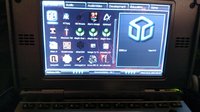
Hello, back again. The new LCD cable just arrived and I quickly assembly it together. It boots up, only with AC charger. It does not start when using battery.
Also, the screen 'color is wired and the touch screen does not work anymore.
I am searching for the short on the PCB right now.
Can anyone help please.
Thank you!
 
It's interesting that it says the battery is at 78%. Has that proven to be stable, or it is going up or down over time?

That screen certainly looks odd, but I'm not sure what backdrop your using. Those red lines look rather like mechanical damage caused by a stylus pressed way too hard and scraped over the surface, or something else hard and relatively pointy.

The touchscreen lines are also part of the LCD cable, so it's possible the cable is defective or incompletely inserted. But thankfully a Pandora is perfectly usable without a touchscreen so I wouldn't worry about that yet and check the unit is stable and isn't discharging that battery alarmingly. Once you'd got that checked over, you can start to worry about more aesthetic or usability type stuff.
 
Those red lines look rather like mechanical damage caused by a stylus pressed way too hard and scraped over the surface, or something else hard and relatively pointy.

That is just the default backdrop in Minimenu

IMG_20170104_131231621.jpg
 
IMG_7734.JPG
Triblelife, how experienced with electronics are you? you can go to the resources tab at the top of the forums its 2 to the right of the forum tab. from ther you can download the schematics of the pandora. this is needed to know if what you measure is what is expected or if its out of spec.
at the top of page 3 at the top left is the area of the PCB that you are looking at . that 682 thing is a 6.8mH inductor on the input to U14 fron VBat. VBat can be measured on pin 9 of U14. out put is on pin 2 and should be 5Vthis is then fed to input pin 2 of U15 output of U15 is on pins 6,7,8 and is the USB host 5V.
i really do not know the pandora circuitry at all just reading the schematics. without decent test equipment and a knowledge of the circuit im not sure how much luck you will have fault finding this. you could end up doing more damage.

EDIT : could you give us a clear picture of J4 ? the USB Host port you resoldered? most of your shots dont have a clear look or its off to the side and in shadow.
Yeah. It is fortune that I can still use the nubs without using the touch screen. The cable is new one which just arrived. I think there are some problems with the PCB, but does not affect normal using. The color could be changed, I think. But the battery level dropped a little bit faster than before. Maybe because of the heat on the PCB. So I can still use it now and try to fix it before the Pyra release. I hope the Pyra gonna release soon, so this old pandora will be retire. Cross finger.
Oh, I forgot to mention that the Color of screen is similar to the one that someone mentioned before. I saw it on the others' thread. This is the picture of the screen of mine.
Thank you!
 
Back
Top