Zikzak - crummiest 8bit console/computer ever .. but I'm making it!


Not had much free time lately, but did a 5 min test. Looks like the stm32f429 driven display is glitching when usart2 serial (Debugging serial) is doing a transmit. I'll have to look into why.. the f429 is a pretty serious chip, with a fair number of improvements/changes relative to the slightly older f405 and f407; the usart2 is on same bus as before, but maybe its causing some congestion somewhere that wasn't on the previous revision or something.

--> I'll look into it

----> but not a big worry, since thats basicly the debug console usart, and..

----> the intention is to drive things via the bus, or another usart, to cpu

Maybe I'll add a serial command for turn on/off the debug responses, so doing little graphics demos driven by PC over usb-serial doesn't glitch on this chip model :p

(interestingly, its only doing this stuff during vblank, so surprising it glitches at all ..)

jeff
 
We're probably all like this? Or am I crazy? but websites with tracking information are like cocaine. "Its in my fucking city, put it on the fucking truck!" <refresh> <refresh> <refresh> <refresh> <refresh> ...repeat refreshing every 1 minute
 
We're probably all like this? Or am I crazy? but websites with tracking information are like cocaine. "Its in my fucking city, put it on the fucking truck!" <refresh> <refresh> <refresh> <refresh> <refresh> ...repeat refreshing every 1 minute
Maybe slightly exaggerated, but only slightly. (thanks for reminding me to check my package, *refresh*)
 
Its a big production for me to leave the house (pack up the kids, then repack them after they need to pee and have a drink, then unpack them at the delivery place, repack them after etc..) .. a whole lot of bother just to get something.. but I get excited, sometimes can't wait; like if you order somethign big.. I ordered a laptop online once.. . and I'd be damned if that package  sits at the depot all weekend :)   Once in awhile you get that thing where it shows up at your local delivery depot (post-sorting) at say 2 mins past the cutoff, where the trucks have all just left.. and a secondary truck group is only for the high rush triple price jobs. So wait for what feels like 4 days (rest of the day, the weekend, and you know like 7pm the monday..), or just call 'em up and say 'hold it, I want to come get it at lunch!' :)

Sometimes you just have to get excited :)

For this guy.. I want to see if my cartridge edge connector fits properly into the pcb, how it all looks (really tight basket weave in the pcb layout but I've learnt that it may look tight in the software, due to all the spacers and such to keep tolerences but looks fine when you get it), and if the ez80 and ZDI ISP/debug interface work okay, so it can be alive; then I can start some basic fiddling, and look at building my own programming interface .. not planning to use Windows for flashing it, thats for sure. Maybe have the GPU flash it, or build a serial flasher, or a PC interface or something.. should be pretty easy. (or spend $99 and get the network based programmer from zilog, that just jacks into your ethernet network and programs out the other end.) Could just leave a little windows laptop turned on beside me to do the programming, mounting a shared disk etc, but thats just goofy if you can avoid it. Building my own interface shouldn't be too bad, and I even envision a cartridge for the purpose.. plug it in, and boot up to a nice monitor application to cruise around memory and run diagnostics, and also features a program to receive 'firmware updates', etc. Or build that into the basic bootloader..

Anyway, pretty excited to see it. Get the z80 going, get the RAM on there, run some basic tests, and then hook it up to the GPU with shared framebuffer in RAM, and get the basic code in place.. I just want to see that z80 drawing lines into the framebuffer, and them showing up on the vga display .. the culmination of a year of midnight-hacking :)

jeff
 
Ahright, the zikzak base pcb rev1 has arrived, and its beautiful!

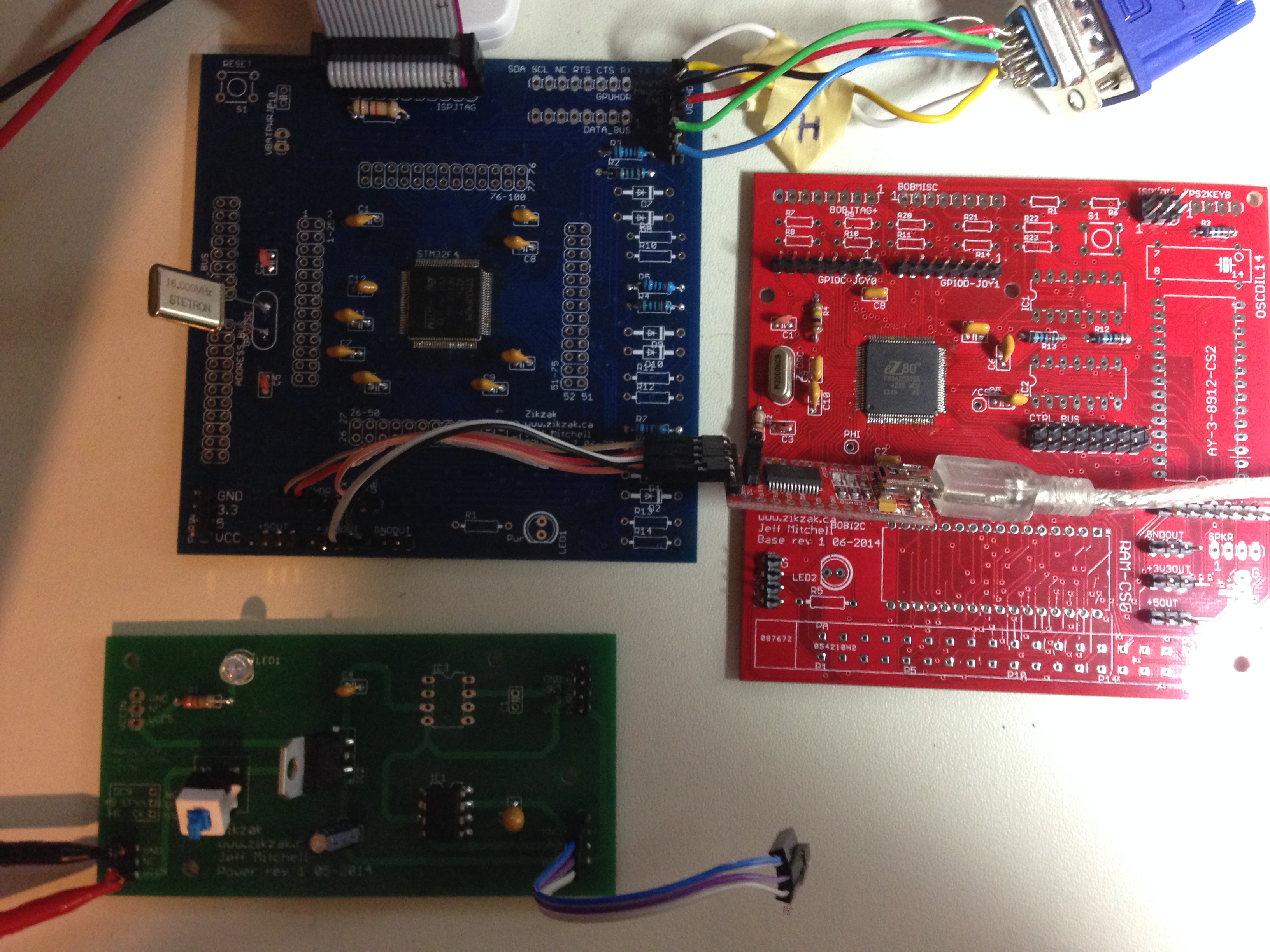
rev1 base pcb -- red

rev2 gpu pcb -- blue

rev1 power pcb -- green

rev1 cart pcb -- green

The edge connector is a little tight (I made the drill holes for its pins too tight, so easy fix for rev2.. but some of the edge connectors fit, so should be enough for testing; also, can just jumper wire them for testing, so no biggy.)

Got the z80 down now, but need to add the decoupling caps and ISP headers before I can see if its alive ... and that'll have to wait a few hours until kids go to bed; time for dinner etc. (blast!)

So, in a few hours, will find out if the z80 part looks right (looking good!), and I'll report back.

Assuming this pcb is good (we'll see!), should be having the full zikzak computer doing 'something' in a few days. z80 -> ram -> gpu -> vga monitor is going to make me really damned happy :)

jeff
 
So far, success!

The eZ80 is seemingly doing what it should; using the Windows ZDS II suite from Zilog (free download, Visual Studio based stuff), can step through the code, pause execution, inspect registers and ram, all that stuff. o-scope on the address bus shows things skipping along as one would expect. This suggests the keyboard, joystick and basic stuff are probably working, leaving the bus stuff as the big question. (Writing code to actually test all these bits on the z80 will take some time.. all my existing per-component tests were with avr, but mostly C code, so should port over fairly well.. like keyboard drivers etc.) The bus stuff is in question since I've never really tested it that way well before, though its pretty straight forward so _should_ work (but the possibility is there I screwed up some of the wiring traces .. not so likely, but possible, since I do this all at 1-2am :) .. and voltage questions, due to the interplay between 3V and 5V chips. Still, that should be overcomable by goofying around between HC, LS, HCT versions of chips (and I've got all the variants on tap in my parts drawers already.)

So, need to work out some code to drive the IOs and check the joystick and keyboard pins, and drive some of the misc pins. Write some code to play with the bus, and watch it on the logic analyser. Then start putting stuf fin one by one.. the external RAM say, first, and test that, along with memory mapping etc. Then drop in the oscilator and AY-3-8912 audio chip and wire in the headphone jack, and see what happens there. Then the GPU, and the real magic test. Then the cart ROM.

So lots of work to do, mostly in software, to start testing.

Oh, maybe write a programmer for linux to zilog zdi, or maybe get lazy and buy the official network based programmer.. with my free time being so limited, it may be worth dropping the $99 to just spare a week or two of fiddling with writing a programmer (which should only take a couple nights, but my nights are way too fragmented.)

---> so, frikkin awesome so far today!

No fancy video yet, but here is a picture of the latest goods as mentioned above..

- rev1 power

- rev2 gpu (blue)

- rev1 base (red)

base1-gpu2-power1-001.jpg
 
In my head, these have always been meant to be side-by-side .. a chain; power -> base -> gpu; (or power -> base + cpu plugin -> gpu); notice how the power pcb has power-out * 2, on its right side; the base has power-in on its left side, and power-out + power-breakouts on right-side (for ad-hoc pull up/downs by jumpers, plus the power chain.) And gpu again has power-in on its left side.

But given these are all more or lase same dimensions (powwer is half-size, but same-width; the gpu + base are both same size) .. why didn't I plan on them being stacked? Right now they need be separate for obvious reasons, but they would look totally sex all stacked 3 pcbs with 1" pcb-risers between. base on bottom has the joystick and cart and such, so not feasible.. but the gpu on bottom is totally feasible. (I actually forgot drill mount holes in the rev2 version (doh), buit it has some spaces.. but not same spaces as the base pcb.)

If I ever do a rev3, I'll have to allign drill holes so there are some in same place, so can mount on top of each other, or beside each other. Mmmmm.

*imagining converting an apple-cube or apple-mini machine into a zikzak, or getting a 3d printer little sexy cube going.. or a little lego box, as is typical for me :)

jeff
 
A Raspberry Pi can get pretty hot, and there's a Lego casing for that. If that's not a problem there, I don't think it is here.

And yes, that's looking great skeezix! Congrats! :)
 
A Raspberry Pi get hot?  I must not be putting mine under enough stress (I have several)... The only way mine would get hot is if I through it in the oven.
 
Lego is okay and you can cement them together with some tricks .. But it does capture heat like crazy so you need to leave openings :)
 
A Raspberry Pi get hot?
You're right, I should have been more specific.


A Raspberry Pi gets hot like a mobile phone gets hot. In my world, that's "pretty hot". An STM32 gets hot like a tamagotchi gets hot. I consider that "not very hot".
 
Not nearly enough time, and the fiddling I'm trying to do takes a lot of it :) Got most of the base cpu board populated (Well, added sockets for everything), and put the OR gates and SRAM on there, and fiddling with the chip-selects and addressing and all that, trying to get the RAM to work; I think the address bus is working okay since I can get the right chunks to fill up, but the data bus isn't acting quite right.. I can write a 0xFF or 0 okay, and various other values, but many values get corrupted. I've got it set up for high wait states, and fiddling with memory write modes. It'll come one of these tries.

The Zilog tools suck. Zilog ZDS-II dev tools are like a crappier Metroworks or Vis Studio, trapped in time 10 years ago; that'd be okay, but they're just really slow for flashing or other activities; you get spoilt by avr, stm32, pic, etc where you hit flash and its gone and done in a blink of an eye (literally.) This sucker takes a good 30s to send over the code, do all its fiddlings with registers etc, and go. Really slows things down.

I'm using so-far the ez80f93, which limits things to 64KB of flash and 4KB of built in SRAM. I had figured minimal is good, since I'm intending on leveraging the external RAM and cart ROM for most of the work; it can run 'in place' in the built in flash and SRAM, but running in the flash means you're burning through your cell writes really fast. At least running your stack etc in SRAM alleviates to some extent. I had hoped to do my basic test fiddling in SRAM entirely without touching the flash, but it seems impractical to start with.. the basic startup code and a peripheral library amounts to 4KB of executable, so can't fit into SRAM as "ROM"; you really need to split it into ROM and RAM space, with enough RAM for the heap and stack and all that and 4K isn't enough. So need to prepare some super minimal libraries of my own and see if I can fit into pure-SRAM...

... but maybe not too much a worry, since my first goal (already got blinking LEDs going as the 'hello world') is to get the external RAM working; once external RAM is going, and I've got 128KB on there, it should be easy pleasey .. assuming the flash tools can update to that, and I can't see why not. Divide it up into 32KB of ROM and 32KB of RAM (say), and good to go, right?

So hence the fiddling with wait states and gunk, trying to see why writing out a '2' comes back as a '3' :)

Once things start working at a basic level, I can start working better.. write my own little bootloader and programmer shim say, or something; be much cooler if I can just open a port in linux and send over the binary and go, just like that, with no 30s or more turnaround waiting for the ZDS-II flash or debugger to screw around. I hate that. Especially when thrashing around in the dark, you want it fast.

Also, I want it under Linux; using Windows sucks, since its not my usual environment, and has its own warts; for whatever reason, I can't get the FTDI drivers installed, and the executable self-installer is a broken download on FTDI site (fail!) .. I really like having serial console logging going on, and its probably how I'd do code uploads and such, so need it to work.

I may break down and order the ethernet/network programmer for $99, just so I can use wine to run the windows ZDS-II, just to keep sane until I get a workaround going; time is so tight, I hate to waste it. I hate to waste $100 even more ;) , but I did sell off a pile of old junk to get money to make my projects easier, so maybe its worth it..

jeff
 
Awesome!

- was writing '1' to external RAM and reading it back as '3'; writing a '2' also came back as '3'; writing 0x0F or 0xFF worked fine. That was last night, and not much sleep, but even last night 1:30am I deduced that gee, 1 and 2 are side bgy side and add to 3, so if 1->3 and 2->3 and 3->3, sure sounds like theres a solder bridge on pins 0+1 or something similar going on .. though had to give up for the night; too much surface area.. linker scripts could've been fooked, my address space definition confused somewhere, PC or stack poitner corruption, any number of things. I was running into oddities like flashing built in flash, and then running from RAM, and it'd run the (old) flashed version instead of RAM version and weird shit, so.. too much surface, brain baked

---> checked now and yes, data bus pins had a bridge on them. Solder wick, microscope, poking around -> fixed! 1->1, 2->2, 3->3, 0xAA->0xAA (1010 1010 is a good binary test I like to use.)

- if including any sort of useful startup code and some mini-libc stuff, your program size is a couple of K; using built in sram of 4K doesn't afford you much space; if you set "ROM" to be in SRAM space, and "RAM" to be in SRAM, and set your stack and heap and stuff in there, you're rrunning tight; very easy to clobber yourself and make it All Go To Hell.

---> once I got the external RAM working, suddenly got 128KB to play with; currently set to 0xAA0000->0xABFFFF address space; force PC to be 0xAA0000 (start of 'ROM', although in RAM) and good to go!

... babies crying, gotta run but..

*AWESOME* .. now just need to write a serial based programmer, and ...

jeff

edit, babies stopped, whew. Stormy outside keeps waking 'em..

Now the bus is proven to work pretty well, I can start thinking about testing the sound chip again, and/or the cart rom. Don't want to use any of the built in SRAM or flash, as its small and precious (I hate using up those limited 1000 write cycles on the built in flash, and its not the point .. want to use external ram/rom as Dobbs intended.)

I mucked up the drill sizes in the edge connector part of pcb, but rather than jump right away and order a rev2 I want to prove this pcb first. Also, it has some $10 of parts soldered onto it already, so why waste it? (yes, I can use hot air rework to get parts out of it, but its fairly troublesome for through hole parts, and my vacuum desolder gun stopped working; cheapo garbage, so gotta fix the pump...)

so need to get a little block of wood, cut out the right hold in it, and screw the edge connector to that; maybne just run some wires over to the edge connector part of pcb and solder them there, but thats sort of ghetto/sloppy, all those wires hanging off it. Be nice if I could solder some female connector on there ghetto style, and then run wires into that.. have to see if I can come up with something.

It is mildly tempting to make a proper cart flasher .. if you recall 6mo or more back I made a perfboard based flasher for the ROMs, so that should work still, but perfboard mass-of-wires tend to break, and be hard to debug; but ultimately, shoudln't need.. the board can flash itself; once I get the serial based programmer going, stick that in as bootloader, and should be able to flash carts directly from command-line on linux, write a little windows UI etc. So skip making a little cart flasher pcb unless people really need it down the road.

Ideally, people should 'need' no programmer hardware at all .. be nice to have, but not needed per se.

... and babies up again
 
Last edited by a moderator:
okay, so I've got a 22pin address bus, 8pin data bus, and 8pin (doubled to 16 for ease of extra jumper wiring) control bus. These are routed on the base/cpu pcb to ram, cart and audio, but need to go offboard to the gpu. Will have to see if I can find 22pin IDC ribbon connectors and >22pin ribbon cables to shred, but for now I guess I can live with just (say) 16bit address sharing .. 64KB of RAM (framebuffer) and cart ROM (sprites etc perhaps.) My eeproms for my own carts right now are 32KB only anyway so no biggy :p

(I've got a pile of 16pin IDC connectors and ribbon cables from some bargain bin..)

So time to make some ribbon cables and hook up the GPU and base/CPU pcb and see if this shit actually works at all. Well, and write some bitbang RAM reading code (easy enough). This'll be the test to show if Any Of This Stuff Works :p

So far so good though!

Just so long as in a hurry to test, I don't have both GPU and CPU trying to write to the bus at the same time; not sure if that'd just cause horrid problems, or actually burn out everything.. so gotta be careful and not find out :)

jeff
 
Really late her and need to sleep, but had to report in..

base/cpu board:

- external RAM working great

- external cart ROM working great!

- joystick 0 and 1 working great

- serial for logging or gpu control working great

--> so at this point can just run the base/cpu board by itself and talking serial to a PC, and run z80 code, use joysticks, all that just fine.

To be done: test the audio chip driven by z80

To be done: test gpu using the bus to grab the cart rom as verification of gpu bussing

(doing the RAM is being annoying due to some stupid things.. the IDC connectors have wide 'wings' on the ends, and I put headers too close together for them; hadn't really thought about it.. was just using jumpers all the time, got stupid.) So need another rev of gpu and base pcb just to space out connectors a bit more ... ARGH!

I'm thinking of also moving the cart edge connector from being vertical, to just being on the side of the pcb; that way the cart edge connector pins which are in two rows, can just squeezxe them and solder them onto pads on top and bottom of the base pcb, not worrying about drilling holesd at all; that lets me use either type of connecvtor (pin or flat-thingies), and is a nice strong connection. But then, can't screw the connector to anything, so .. hmm. Maybe I can make the pcb do both options...

Anyway, too late at night now, so will trial the gpu reading the cart rom tomorrow or friday; have to figure out a workaround for the RAM, since reading the framebuffer off ram is the whole point after all. I mean, another pcb rev wouldf make it easy, but I dont' want to wait 2 weeks or spend another $25 for that rev, just yet :) I could perhaps use the cart rom as framebuffer (Slow, sort of nasty), but it'd do the job for testing the system I guess.

Still, all told, this is really sexy imho.

I mean, can run the serial (there are two serials on here) over to gpu and just run it that way; that'd be fine really, since gpu has enough space to store sprites, and it can read rthe cart rom anyway direct, so don't need to send all that much over to the gpu. But still, a true ram framebuffer is awesome, so can do effects and junk in the cpu direct.  Its tempting to take a 'break' from all this hardware side, and write a shitty space invader game driving gpu over serial but..

--> keeps at it, once this bus shit is proven, wer're in the home stretch.

Audio is a pain to test, since I suck at audio, but got some hello world type lame sound effects to try out.

Frak, I can't believe I'm running out of things to test; so far so good, its all working :)

Will post a pic tomorrow.. sleep now!

jeff
 
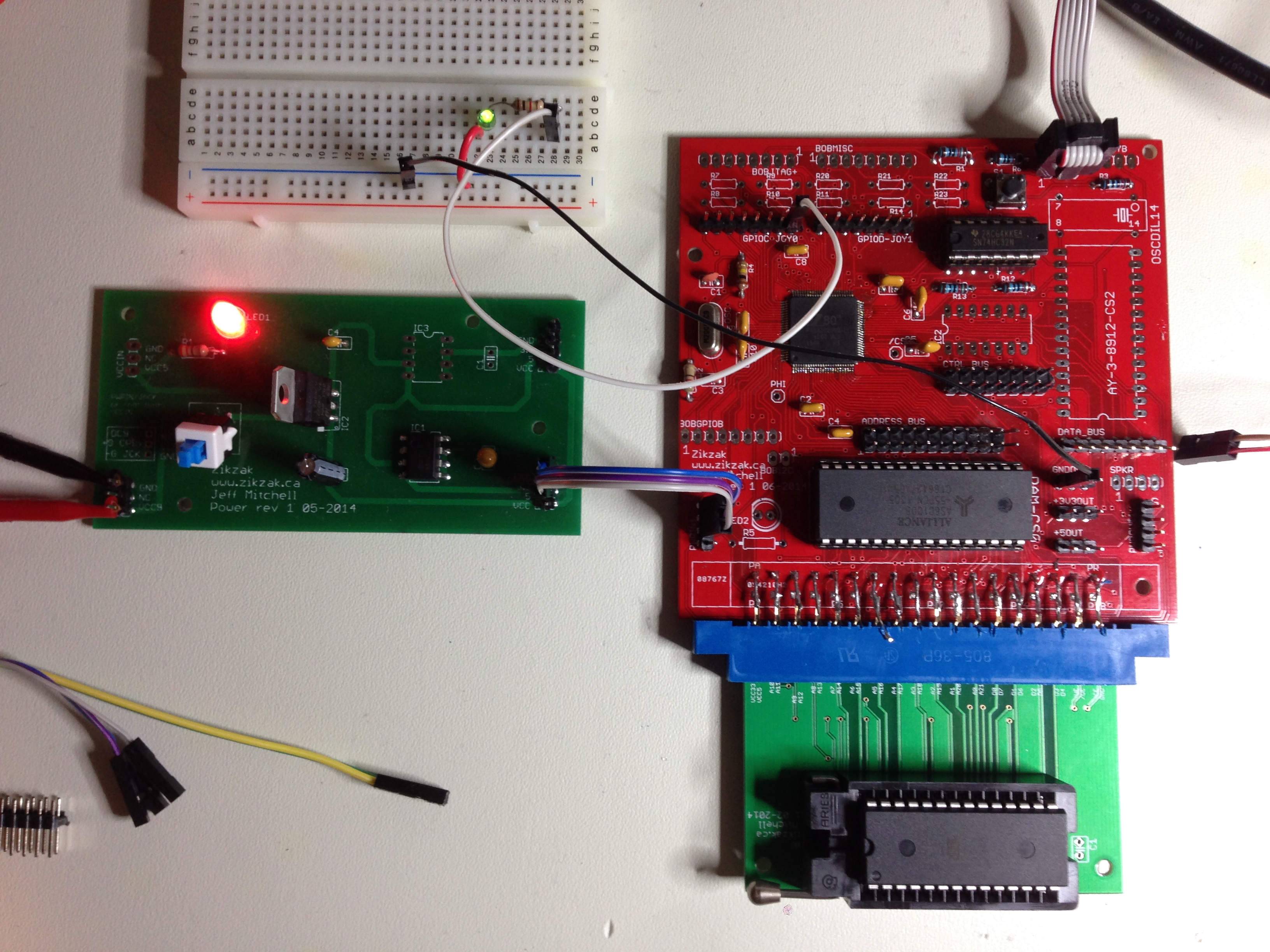
Here you go, photo from last night .. the base/cpu pcb, with RAM installed, and a eeprom cartridge plugged in. Maybe not exciting to anyone else, but pretty slick to me :)

GPU board is not in place here at all as you can see . retreated to test the bus and peripherals; next up either the audio chip or GPU hookup if I can work around the connector-proximity problem cleanly. (I really don't want to run like 22-30 wires soldered from the board .. just so messy when you need to flip it over a lot to test things etc..) ..

zikbase_with_cart_001.jpg
 
Last edited by a moderator:
I've done a minor update to the website .. ditched the tabbed interface and replaced it with a basic left-side sidebar menu. Should make things easier to use, as that tab system stunk the place up :)

I need to redo the content and update it etc, but let me know if the site navigation is at least not-suck now..

http://www.zikzak.ca

jeff
 
oh and I had a 'duh' moment; so if the current rev 2 GPU pcb has the headers too close together to get IDC connectors on them (sadface), a possibly easy thing to do is..

1) Put one of the headers on the _bottom_; this would reverse the connector, but could flip the ribbon cable over; I didn't sdleep enough lately to work that out in ym head, but strikes me should work :p

2) Or just make some female header perfboard-to-IDC-adaptor thingies; sort of a drag, but may do in a pinch. Got a stack of credit card sized perfboards (like 50 of them) for a reason :)

jeff
 
Back
Top