Zikzak - crummiest 8bit console/computer ever .. but I'm making it!


I've waffled on that very point many times; if you read the whole thread, I'm sure you'd see a pattern of indecision.. one big board! a separate gpu board, cpu board, power board, I/O board! No, how about a power and amp board, and cpu+gpu board! ... etc :) Theres convenience vs cost vs placement advantage and such as well.

The sweet spot for pcbs these days is still 4"-square or less (10cm and less to a side); so, I've often liked the idea of a stack of 2 4"-square boards. I've even gone so far as to do a buss up one side, so that 2 or 3 or 4 boards could sandwhich together like that.. a cpu board, a gpu board, a power/audio board, an expansion/cart board on top. Think of the madness! I went once to the extreme, wher eyou could even stack multiple cpu boards ... and even so far as a crazy bus, where you could put like 32 cpu boards together for some crazy fun....

The trick of course is that microcontrollers, with the pincounts I need (100+), are pretty 'big' (their footprint, plkus the necessary space around them for the routed paths), so putting two of them on the same 4" surface is hard. But as they're smt, there _is_ the possibility of doing one on each side, but I find I need those vias and both sides to do the horrid routing. This of course is why modern pcbs are 4+ layers thick, so you can jam things in good and route all around no problem.

So, hence why I've settled on 6"x4" .. a little pricier, but at least its got the space to put the two chips on there, and also enough for a bunch of support stuff.

But yes, I could do a r4 with various combinations..
- a base 6"x4" board with most of the good stuff
- a shield that goes on, for all the jacks and breakout
--> but designed for this purpose

ie: group all the headers together in some central location, or convenient location (elevator shaft like).

Making r3 was _Really_ tough routing, because its a metric hellpile of traces; also, the chip pinouts are really bizarre.. like, you'd think they'd be in bamks of 8, like on 8bit chips like the atmel avrs .. so GPIO "bank A" would be A0-A7, right? But on these high pincount chips, they're will nilly, 100 or 144 pins all in a big random mess more or less. Seems to me like they lay out the internal mess and when they add the physical pins on, its 'best they can do, without much of a fight/cost'; real boards are BGA surface mount and auto-routed by million dollar software so who cares right? But us hobbyists agonizing ove cost and every trace, it hurts like hell :)

And as noted, making the eagle cad library for these little jacks and parts is fiddly work; so making this shield for r3 is really just a way to move forward 'path of least resistance'; its easy to make the shield, and forces me to get the library drawn up; then I can get it made, and see if the library stuff is actually all right, the holes are in the right palce and measured right, and the pads connect to the right pins on the schematic, and the schematic circuits are all right, and etc etc; if the shield actually works (or has minor flaws easily corrected, or iterate a few revisions to get it right..), then you prove all that stuff.

After that, then if we still want a r4, we can plan that out and attack that, with having all the foundations again proved. Step by step, less risk; more time, but easier bites to make.

I'm one of those bloodyminded determined people, put one step in front of the next to get through the storm; real life makes no free time, but I'll be damed if I dont' make some progress any way I can. So this is what works for me :)

I'll probably end up making an r4 "all in one pcb" or maybe two board as above, anyway, of course, since its all fun :) But for now, r3 (already have it, and got one working a treat!), so just put together a $50-for-10 shield, populate one, and see how it goes!

As you can see above, its already half done, and the hard part is out of the way; I know how I'm going to power it, and the power+usb+amp+ftdi circuit is already actually all schematiced up; the jacks and such are modeled and all on the schem and pcb; I need to worry over placement, and route all the unrouted traces .. but routing on that is a cakewalk! Routing could take a night or two only and done.

So, plowing ahead ... but not too fast, don't really want to screw up; need to check, re-check, re-re-check :) check the design rules, make sure nothing is too close; print out on printer, plug jacks and such through paper, amke sure things all fit and the physical real world casings and such don't get in the way in unpredicted fashion. Make sure it qll lines up between layers, and that the things fit vertically with no bits too tall for the header pins I'm meaning to try to use. I'm not using real board to board interconnects.. just really tall header pins, so need to measure it all out.

Still lots to do, but I enjoy it, for some reason :)
[doublepost=1463197753,1463195625][/doublepost]Redid the top edge (not cart side, the other one) milling; since that big block was really just to ensure theres space for te ZDI and JTAG .. rather than block out the whole top edge, just mill out right over those two spots. (Theres more header pins there, BOBJTAG+ and BOBMISC, but I don't really plan on using any of those pins; and if I do, could just run jumpers from the ZZr3 base pcb anyway. So, if I leave most of that top edge present, milling out just over the ZDI and JTAG headers themselves ad a bit more, it buys me back a bunch of edge space.. just enough to put JOY1 (second) and VGA between the ZDI and JTAG; I can get the PS/2 keyb connector on the back (top left, beside the power/serial USB) and then put the data USB on back (top right), which has the right symmetry to make me happy. The only wonky stuff then is the thumbwheel for volume, and the uSD, which are both sort of stranded in the middle-right, when they should be on the edge. Now mind you, they're still operable in the middle, which is fine; and uSD could even be left like that.. just stick an SD in there and not worry about it, right? But the thumbwheel I really would prefer to be exposed, so if I 3d print a case, it could be used :)

Anyway, need to relax a bit, will worry about this more over the weekend. Need to print it out on the ink printer, plop jacks into the paper, and see how it feels in the real world.

jeff
[doublepost=1463198818][/doublepost]and FWIW .. still adding subsets of the forum posts here, to the dev blog; you may want to also follow there:

http://zikzak.ca/dokuwiki/doku.php?id=devblog
 
Stacked up a couple pcbs with the long header pins I intend to use for bridging the two boards .. plenty of clearance, like a full inch; should be no problem reaching the ZDI and JTAG out the back, without milling any extra clearance holes in.

Given that, the whole back of the shield can be jacks, which makes things work out really really nicely; left side is now headphone and joy0 (right where you want them!), with the back side having USB (power/serial), VGA, joy1, USB (OTG); right side, rearish has barrel jack, and right side near front edge is micro-SD slot. Front edge is barren, but the front-top of course is dominated by cart slot.

I'm envisioning the case to have a little L-shape flap on front-top lip, so you can flip up the L to reveal the slot. It'll look like a little box, cutouts for jacks mostly on the left and back, and the flap for the cart slot. Most of the shield (middle through to front) will be milled out, to give heat somewhere to go (there shouldn't be much anyway..), and to ensure space for cart casing.

Will post updated board layout in a little while, but looking pretty swank! Gotta admit, I'm getting a little excited for this pcb now .. be sweet as hell to have a (if it works ;) usable unit thats a one-piece-does-it-all like a real machine; slapping together a rudimentary box case and printing it out shouldnt be tooooo bad from there, then the decision about ZZ rev 4 or not. But still, feeld like we're not that far from a final fully homemade cased unit.

jeff
 
For those keeping track..

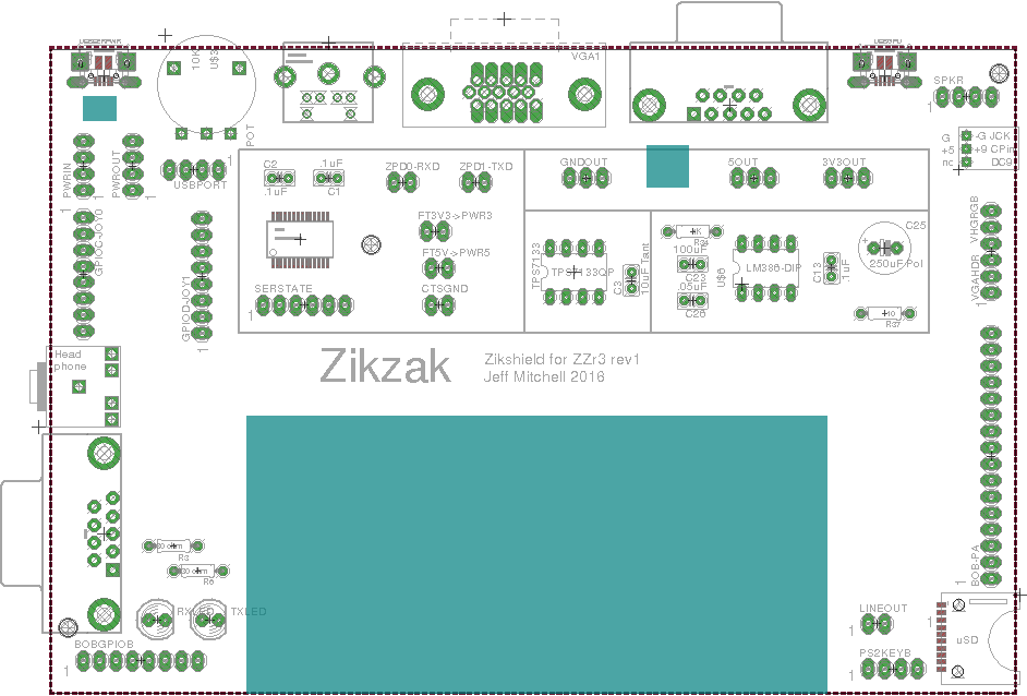
Image of the layout so far; the big gaping hole in the middle/bottom is just for airflow, and as space where the cart passes through into the Zikzak r3 pcb below
zzr3-shield-r1-layout-wip-002.png

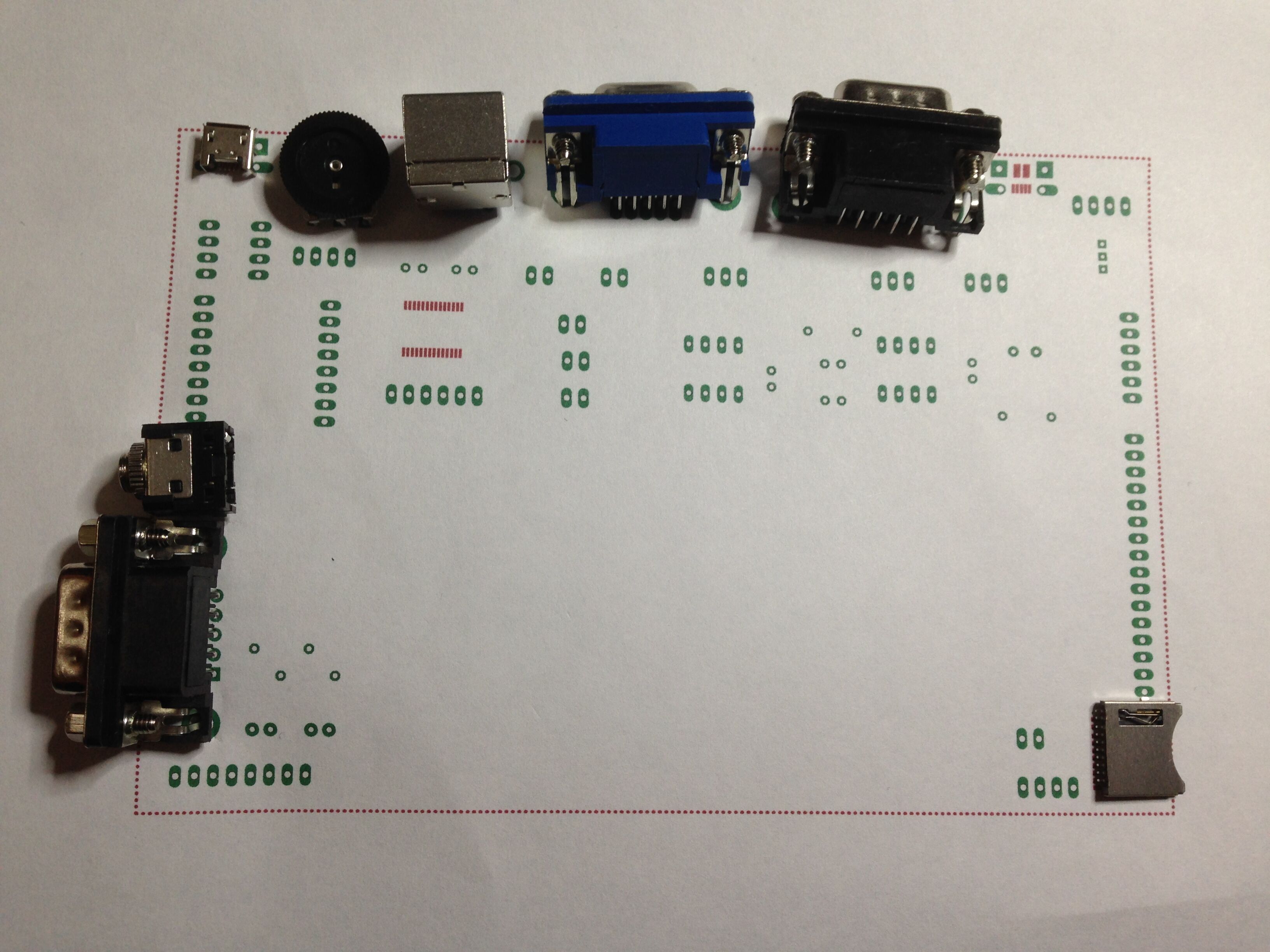
And a lame photo of a printout of the pads, with connectors laid about; thats just to ensure there is sufficient space around them to actually fit. Little tight in front left, with joy0 + headphone .. think I can move them about 1-2mm apart more, is it, due to the bridging header pin constraints.
zikshield-wip-002-with-connectors.jpg
[doublepost=1463429461,1463429300][/doublepost]FWIW, the blue is milled cutouts; the two little ones are just to expose the reset buttons in the ZZr3 below the shield, since it can be handy to poke them. Sort of lame, but the whole shield approach is goofy :) .. but at least, sticking a pencil down there to reset is doable.

I'll do the pcb routing ASAP, and after checking the design rule constraints and such, should be ready to send to the boardhouse.. then wait 2 weeks, and go from there! Its pretty hard on the boardhouse to put in the USB pads.. so damned tiny. Just in case they fubar it or can't, I've put in a 4 pin header for USB, so in a pinch I can still test the pcb with jumpered USB jack while doing a rev2 or something.

But yeah, if this shiel works out okay, I'll almost certainly get fired up about doing a rev4 ZZ base, that is all in one, the works.

jeff
 
Ahright, after a very fast route job (it takes a fair amount of work to weave every little trace around in a basketweave .. I worked hard at it, but not slowly thats for sure ;) .. but it passes all the ERC (electrical rules checks) and DRCs (Design Rule Checks, the physical spacing between traces and holes/vias, the width of traces, etc and so on.) .. so, nearly time to send to boardhouse. I'll take a breather, and then re-verify the schematic as its very easy to miss subtle little details, but seems likely I can send to boardhouse tonight! Then its wait a couple weeks, then populate it, and then a couple weeks of writing test code to check various pieces ... good times!

Nearly there :)

jeff
 
I've only had a few minutes to eyeball it, but I'm pretty happy so far. The jacks seem to all fit into their respective holes (huge win imho ;), so its really s question of did I wire it all up correctly, and map the pads to schematic elements correctly, and all that. Will find out 'soon' .. been up most of the last two nights with sick kids and exhausted, and lots of RL work the next couple days (blast!) .. who expected to place and order and have the thing in my sweaty hands exactly one week later, from other side of the world? Yay for modern times! (and again, goo Elecrow!)

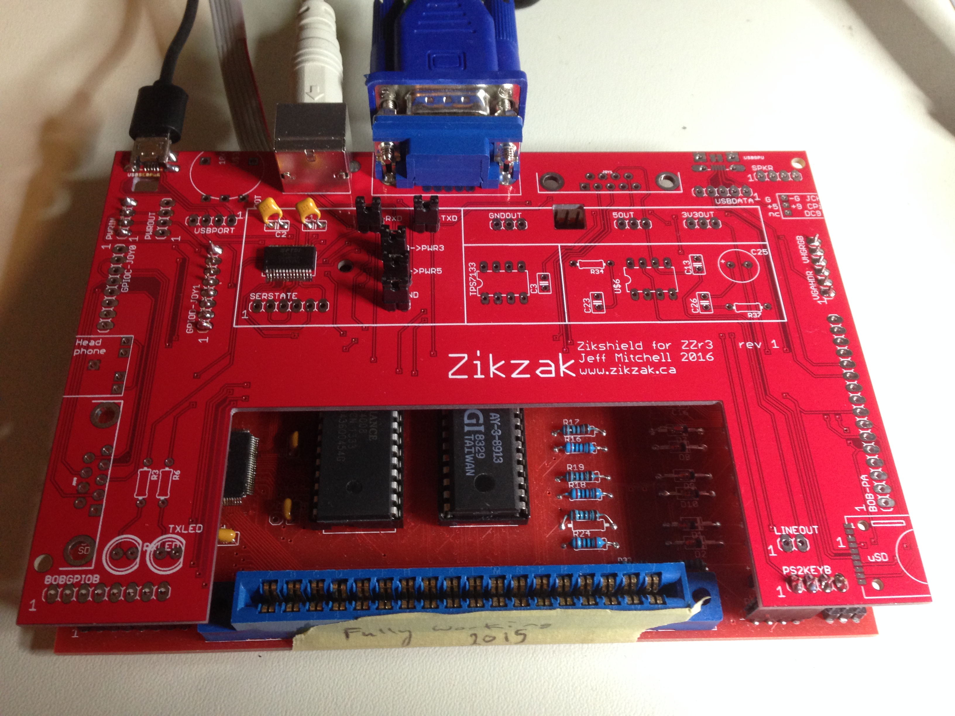
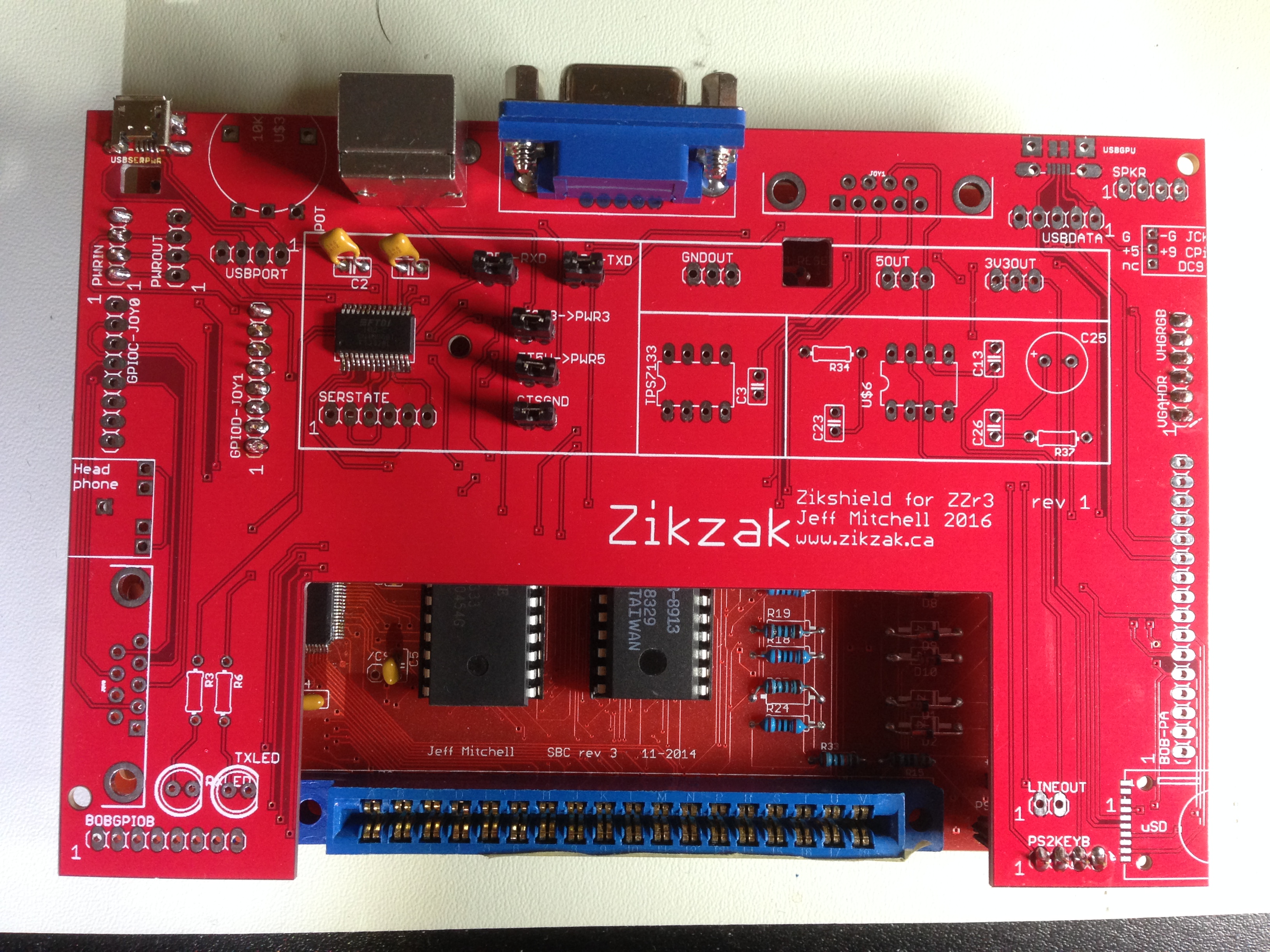
Here is the unpopulated shield, fresh from the box ..

Photo%20May%2024%2C%206%2041%2055%20PM.jpg

[doublepost=1464136315,1464135750][/doublepost](And yeeesssss I know that its a dumb-as-hell layout, due to all the constraints mentioned above; also, I rushed it real bad :) ... imagine having the headphone hack on one side of the board, with the amp circuitry on the other side, and the line-out down near another side? Talk about asking for interference in the audio signalling ... but hey, just wanted to pop out a quick board to test all the newly added circuits, custom jack CAD stuff, etc, and make my life easier.

So whats next?

- testing and testing, and.. hope you like more testing!
- if horrible flaws, just jumper work arounds and correct the CAD work...
- design and print out a nice little case for this bugger; be pretty sweet to have a little single box 100% homemade console/computer; plug in power, and video, good to go!
- decide.. going for ZZ rev4 with all this stuff on one big pcb (possibly even 8"x4"!?) .... or a two board solution again, but designed on purpose for that instead og haphazard as this?
- really should make an actual Space Invaders mini game instead of just my million little testing tech demos; should also print out a cart box and game artwork sticker
- sort of implies a bit more work on build in SkeeBASIC and basic firmware/BIOS stuff...

But my first goal is hardware, so I can at least call it 'done' ("done enough"). It takes quite a while to test all this especially as Zikshield here added a lot of stuff that was entirely out of scope ("left for future expansion") so is entirely untried. ie: SD slot. Was always on the 'be cool if I ...' pile, and here its gone and been hooked up. Who knows if the circuit is remotely right? Likewise for data USB" (USB OTG...) .. can this z80 computer really host a hard drive or usb thumb drive? or ... Ethernet etc? Think of the sick shit we could do...

jeff
[doublepost=1464136726][/doublepost]Psh Psh .. all this excitement over the Pyra, and here we're putting together a Super Shitty (not just any shitty, but Super Shitty!) homemade machine, documented since inception on the boards :)
 
Can a z80 even drive a USB1.1 port at hi-speed, which is what, 11Mb/s IIRC. I can't remember my z80 opcode timings, but it's probably something like 3 ticks to write to ram, plus another couple ticks even to alternate 1/0, and you're looking at needing to run your processor at 55MHz.

Regarding the shield design, I'm a fan, but suspect it'd probably make more sense mechanically to have to ports and power reg etc. on the bottom board and the guts on the daughterboard, rather than t'other t'way t'round. Just imagining what lugging on a screwed in VGA cable is going to do to that connection between the two boards. That VGA socket and the two DE-9s could be bolted to the case I guess to give it more stability, but a rickety case and different parts bound to different parts of the case could still spell trouble.

Edit: USB hi-speed is 12Mb/s, but there's also low-speed which is 1.5Mb/s. God knows what support for that is these days though.
 
Last edited:
Psh Psh .. all this excitement over the Pyra, and here we're putting together a Super Shitty (not just any shitty, but Super Shitty!) homemade machine, documented since inception on the boards
Great work. I really want to build one of these now. I've thought a lot about building a Z80 machine lately because I am working on a Galaga Arcade machine with three Z80 in it. I look forward to my alerts that you have posted more information.
 
Can a z80 even drive a USB1.1 port at hi-speed, which is what, 11Mb/s IIRC. I can't remember my z80 opcode timings, but it's probably something like 3 ticks to write to ram, plus another couple ticks even to alternate 1/0, and you're looking at needing to run your processor at 55MHz.

To be fair, I'm actually going to drive the USB from the stm32 "GPU" these days, which is cheating (recall the Zikzak has fairly strict rules about non-cheating, otherwise ther whole thign just turns into a SoC single chip machine.) .. but USB is not a priority whatsoever, so I took out the extra bits I was going to do for z80->usb, and just let the GPU-side do it, if someone wants to build that. I'll have to build some minor test, but not planning on going down the road much myself.. just no time. The STM32 has USB controller built in. And yes, bitbanging USB with an eZ80 is doable (badly) .. the eZ80s can be gotten at pretty fast speeds (like 30MHz), but it certainly isn't ideal. Think USB keyboard level signalling, but not useul for mass storage, but the STM32 should be able to handle it, however, theres other limiting factors there since I didn't design the GPU-side to do much beyond GPU-work :)

Regarding the shield design, I'm a fan, but suspect it'd probably make more sense mechanically to have to ports and power reg etc. on the bottom board and the guts on the daughterboard, rather than t'other t'way t'round. Just imagining what lugging on a screwed in VGA cable is going to do to that connection between the two boards. That VGA socket and the two DE-9s could be bolted to the case I guess to give it more stability, but a rickety case and different parts bound to different parts of the case could still spell trouble.

Oh its certainly not the way I would do it, if it were designed this way; this is purely an evolutionary step "from preceeding step", and the just a way to 'move forward, in the absence of time'; call it a debug board (I'm a software guy, so learning electroncis is just a fun hobby, and I approach it like software.. so this is just a debug iteration). Real life time has been so brutal for a long time, I didn't want the project to just sit idle any longer.. so as a way to move forward 'at all', I knocked out this board just to test my CAD packages and schem->package mappings, and the new circuits (on-pcb amp and ftdi and all that.)

edit: btw, given jsut using tall header pins as the b2b connector, its going to be fragile.. push roughyl on a VGA plug, and it'll knock the boards apart, right? But this is just for on-bench testing, and I figure if I make a little case for it just to make it look cool and carry around, then I can use some thicker walls and supports, so the case itself should provide some structure; ie: keep the boards pressed down together, and limit the side to side motion that way. Its dorky, for sure, but we'll see. I just am sick of jumper wires al over my bench, as they do come apart, for sure :)

The ZZr3 main pcb was intended to have a separate power board or brick (I have a little power board that spits out VCC, 5v, 3.3V, 1.8V and gnd), and have all its jacks via jumpers, with the jacks screwed onto the case. But in practice, when I printed out thin walled plastic case, the jacks screwing in would just rip up the plastic pretty easily, and all those jumpers were just a mess. Modern boards all have the jacks right on the PCB for good reason :)

So rather than do a proper ZZ rev4 with all the jacks on there, I just threw together this shield board as a quick experiment; help prove things, and be fun! Its also relatively low cost - making a main ZZ board costs a fair amount since it has the eZ80, STM32 and other goodies on it. The shield is mostly passives and jacks .. just a breakout board, with a cheap FTDI and LM386 thrown on. I'll probably only ever use 1 out of the 10 I ordered, but its a good fun debug step. And I can throw a case on it, and it'll all look cool.

Even if its lame.

...

As to the future .. do I go one larger do it all PCB? Or a multiboard .. 2 boards say? 4" square boards are cheap as hell to knock out (10 for $10), where as a 4x6" is about $45 for 10, and 4"x8" is like $55 or so. Starting to add up.

I gully agree, the jacks should be on a stiff board, and I think the operational groups should be close -- the amp and the headphone jack and line out and volume wheel should all be in a cluster, etc. But due to the evolution, how we got here, it just wasn't feasible "today".

..

Its all about having fun and hacking around, and keeping it moving, right? Its one thing I'm good at.. plugging ahead, against all odds, in the time I have.

jeff
[doublepost=1464189849,1464189548][/doublepost]I'm half tempted to order (ebay) more jacks in .. I think I have 10 of each, but if I end up doing a few iterations, maybe I shoudl have another 10 or 20 on hand of each, since they're pretty cheap. Be really annoying to suddenly have 5 or 10 of you guys want a board, and then have to go find matching bits and bobs..

jeff
 
I think if there's one thing everyone in this place is relatively practised at, it's waiting for stuff ;)

As I say, I think splitting stuff between two boards will make for a better looking machine. Also, all of my 8-, 16- and 32- bit machines were stuffed full of little daughter boards by the time I'd finished with them, so it's a suitably retro idea to me. And of course it's something the Pyra's doing too.
 
Only had a few minutes, but I put the power/serial USB jack on; needs a pile of solder, takes a fair amount of force when putting in/out the cable! .. and FTDI and VGA jack, and the damned thing comes up when the boards are put together. I gotta say .. dorky as it is, it looks pretty sweet :)

I'll see about putting a few more jacks on there ASAP and get a pic up. *hawt*

jeff

Ended up staying up waaaay too late in the morning debugging what turns out to be soldering; putting that USB smt connector on is a real pita.. just too small (pitch, and also the physical size of the pins.) Just really hard to get them soldered down reliably. Also need big pools of solder on the casing to keep it strong on the pcb, but thats easy. The FTDI chip I also had a inconsistent joint so it was flaking in and out .. realized that when I held it down and everything worked :)

Again, saved by the USB microscope. Zoom in close, do very specific solders and inspections, and got it sorted!
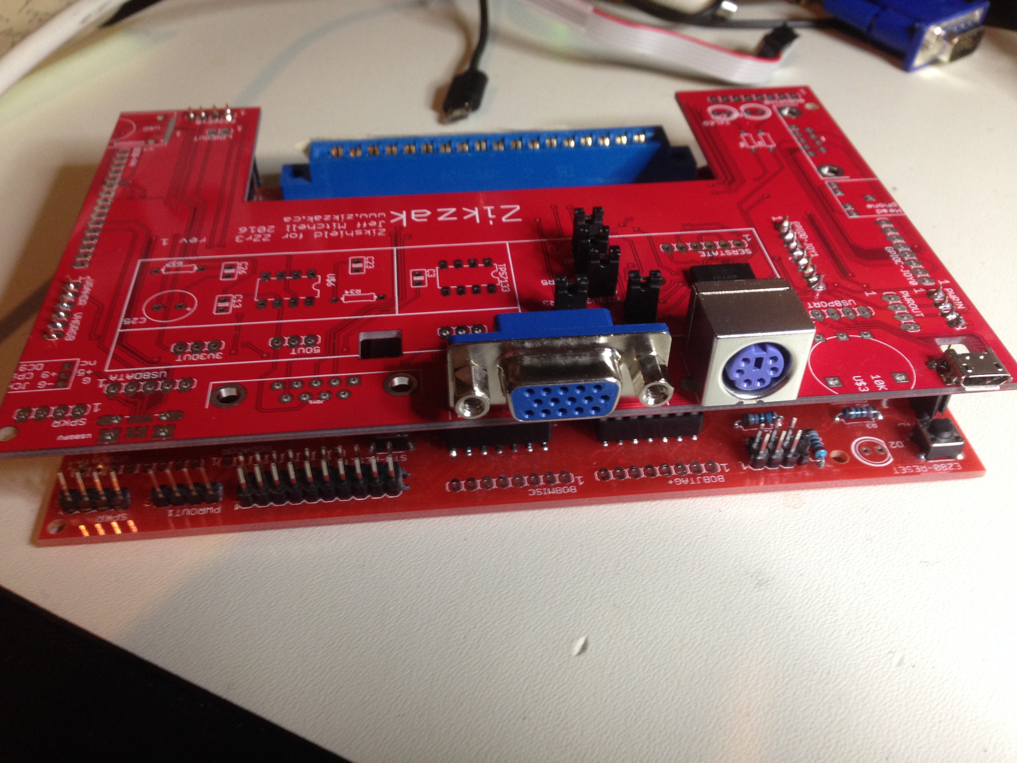
[doublepost=1464281080,1464276807][/doublepost]okay, here is your ZZ hardware porn of the day; its only partly populated (PS/2 keyboard, VGA, USB power/serial), but so far its working perfectly (yay!) .. ad imho, even though its a goofy layout, its still sexy as hell :)

It'll look even better with the rest of the components and board2board connectors on :)

A pile of photos follow:
zikshield%20r1%20on%20ZZr3%20-%20001%20-%20hooked%20up.jpg


zikshield%20r1%20on%20ZZr3%20-%20001%20-%20rear%20side.jpg


zikshield%20r1%20on%20ZZr3%20-%20001%20-%20top.jpg
[doublepost=1464283692][/doublepost]If only there was a market for this; I really should try to marketize it somehow .. roll out a first actual game, try to make some easy to access libraries etc, tie into Arduino or something :O
 
To be clear.. 'working so far' is in reference to the Zikshield; the ZZr3 has always been working very well, for quite some time (a year?) .. so I'm specifically talking about adding new circuitry (amp, ftdi etc) on board to the shield, plus the jacks and extras. So working so far .. the shield new stuff so far (FTDI say, for power and seiral, without using an external FTDI Basic type board from ebay) is working great.
Working as 'desired' :)


uSD is not a priority for me .. thats just a fun 'hey, we can do that' so I've kept pins available "should I ever want to go there", and for Zikshield I figured I'd add it on.

The main goal is (WAS?) still very retro .. cart for ROM.
+ mind you, I cheat a lot here, as the eZ80 and STM32 both have flash built in (and by flash, I mean realtime updatable by ISP prgrammers, or even from the cart, or over serial if I write a flash tool, which I intend to do in the built in firmware.)

So what is done now is .. flash in basic firmware ("hacks", the random test code) to each of those processors; the stm32 firmware basicly pretends to be a gpu, and runs down the memory map and spits out video. The eZ80 side is iether specific test code, or a very basic memory mapped BIOS (thoguh this is just very preliminary and needs a tonne of work; I'm trying to avoid writing it in ASM as I just do't have time in the day, but a basic C BIOS should be doable.)

The eZ80 firmware should in effect come alive, try to determine how much RAM there is and what peripherals are available, check for presence of a cart .. if present, jump into the cart; if not, go into demo cycle with menu, so you can go into somethig like a BASIC interp or built i minigame, or have it do various self tests (ie: let you waggle joystick to test it, etc.)

I had itended that BoB shields could be added to add on other peripherals, or even expand off the cart .. ie: add an SD and mcu to the cart, for say mp3 player or something.

Of course, now that I'm going to do basic SD testing now, theres nothing saying for rev4 we might just put the SD on as standard option, and make the eZ80 firmware able to read and ru code from _that_. ie: copy a program into RAM and then jump into it, rather than just run in-place from cart.

There are TBDs there though; as SD was not the focus up front, it has some limits (ie: it shares some pins with audio due to the limited chips I used), so its conceivable certain operations could confuse things nicely there, but more or less it should work today, as is.

Theres a lot of 'risks' all across, since its just a hack friendly test board right off; ie: due to the zikzak design non-cheating rules, the GPU is all bitbanging to get at the external bus (for video data etc), which colours how the system works a lot; if we switched to a fancier chip that can just mount the bus directly, things woudl perform infinitely faster.. but I called that 'cheating'. The goal here has never been high performance (ie: see Pandora instead :), but to have a fully open system, where the user has to have some idea whats going on to build it and code it (since they have to make some choices), and can learn about the whole thing. Or just get one, slap a cart i, and fire up a lame game :)

ie: For assembly, I've left a lot of options on .. like: you can power it this wya, or that way, or this other way; you need jumpers to switch on one way or another, or in some cases you just populate one chip or another, but not all, sort of thing; if you end up populating everything or jumpering wrong, you fry it. So, if we send a baggie of pcbs and parts to someone, I need to include a thin manual that saus put THIS, OR THAT, OR THIS OTHER THING depending what you want to do. Or if we gave a finished unit to someone, it woudl be 'standard config', with no options, like any other machine out there.

So, yeah, its goal is cart based, with flash for built in code.

Expndable as hell (given someone writes it..)
.. or pick up programs from SD
.. or serial
.. or USB :)

I expect a common use case would be for people to just flash games/things right onto the eZ80 (and more or less leave the GPU side alone, though peopel could flash it to udate it, or run it as a second processor in parallel to the eZ80 .. or as a slave/etc), which is my typical mode of operation. ie: I don't usually bother to flash tecart (using Zikburner), or put it i the ZZr3 and flash it from there (have done) .. I just just use the z80 dev kit, hit F5 to deploy the code over ISP to the eZ80, and call it a day. But theres nothing wrong with having the eZ80 firmware have 'upload to cart' option, and then stream across USB/serial from PC to the cart. ZZ is its own devkit, of course :)
 
Ah, so it's not like a NES or something which started by jumping to the first address in masked rom in the cart port. It's retro like a GBA or something that has a bootloader, which I guess means you can use cheap NAND flash in the cart, and not be bound to NOR flash or, god forfend, actual masked roms, and load stuff into RAM before executing it.
 
yes, quite so. Early on I wanted carts to more or less act like RAM .. so they can be ROM, or eeproms, or any number of things that the bootloader could set up .. but for now the carts I've been using are the old atmel flash that are read/write exactly like RAM (just slower for writes). This way we can treat them like carts and yet are easily reflashed (ie: rewritten) in place right from the ZZ itself... remarkably handy.

Using an EPROM would suck; theres retro, and then theres just making your life painful for no reason. When I'm repairing an old arcade board, sure, use a 2316 or whatever EPROM, but for ZZ.. no way :)

jeff
 
I must admit, I don't really understand why you can't use NAND flash as an addressable space you can run code in place. I guess it's the same way you can't run programs from discs without loading them to RAM - the interface just doesn't let you wire up address lines and chip select lines and so on.

But this atmel flash you can wire up like that? But you're still going to have a bootloader - well I guess you may as well as it lets you do all kind of modern things like insert breakpoints.
 
... and, there are billions of options. So, you pick one that matches your goals, and try it out, and go from there. I wanted to avoid anything with 'high power needed to flash' or separate flashers, and I really like the 'flash that acts like RAM' .. it keeps things easy. But, I also designed a cart interface since it'd be fun and retro and in-line with my goals .. but also, it lets you go nuts with the cart. You could just slap an mcu on there instead of a RAM/ROM/flash/whatever, and that in turn could just pretend to be a eeprom. It could in fact, do something else entirely! .. so by having a cart expansion interface, you can do crazy experiments.. if you want.

.. and thats what its all about, right?

Mad science!
 
Case design is coming along pretty rapidly; I mean, I'm no designer, and using 3d printing puts a lot of limits on you. ie: You have a hard time doing rasied areas or concaves etc .. and the plastic I'm using is fairly strong but brittle (doesn't bend), so if you have jacks all over.. you can't bend it to make the pcb fit in (the jacks protrude from the pcb). So you can't just slide a U down over top of the board, if jacks are on both sides ... but if you make the box bigger the jacks may be recesed too much; too small, and nowhere for screws to go, etc.

So I'm just making a two-U box with air holes all over it, and some spacing for screws, and cutouts for half the jacks (too lazy to model all of it, and I won't need all the jacks till later anyway.) Still, I hope to get a prototype case just to protect this, and look cooler, soon.

Jury duty and other real life will be in the way for a few days though.. sigh.

jeff

edit: sorry, rushed post; I really dig OpenSCAD .. a CAD where you have to script everything, like HTML declarative code with a simple programming language within. Most CADs I've tried are brutal - nasty nasty UIS, and very high complexity, coupled with a lot of ... isms, specific to that software. FreeCAD is like that .. very goofy to use, either too much or not enough docs, lots of seeming bugs, and what I think should be simple turns out to be annoying or hard. (Really, with most 3d modellign CADs, just getting working rulers/annotations going is a nightmare.. why? Shouldn't that be first step for mechanical drawings (as opposed to fluid free form drawing..)) .. DesignSpark Mechanical looks amazing, and its whole ease of push/pull is astounding to turn 2d into 3d .. but again, ruler hell. Its easy to draw a rect, then pull it into a 3d-rect, and then turn it into a shell and adjust widths to create a box.. great! But then to refine things, it seems very imprecise and its a real bitch to work with dynamic measurements, or to add annotatiosn, and so on.

But OpenSCAD is right up my coder hearts road; just start entering specific values, and since its declarative code, can make everything relative to variables you set up top, and you can have conditionals (if statements) and macros and so on; so for instance... I have a preview set of script to scale it down to small size for printing (why waste plastic?), and an option to invert everything (when printing the top, you want the flat surface on the bottom so it doesn't just droop down), size of holes for airflow and other resolution options, etc. So right at top of script, can tweak it.. include whole box? or just some parts of it? and how big? Tweak a few variables and the CAD just dutifully renders. Precision is absolute.. just type in your measurements, and no 'loosy goosyness'.

OpenSCAD is hard for non-coders perhaps, but its a dream for me :)
 
Last edited:
  • Like
Reactions: rSl
Back
Top