<brain dump mode>
Didn't work it out yet, and as it seemed a non-useufl extra block, haven't pursued it. I don't have a handy TRRS male on my benchtop, but maybe those are longer and protrude into the 6p block; or perhaps theres some custom connector that goes in there, or something. No idea where I got these from

I originally thought they'd be pin duplicators .. to get a nice 2x3 grid of simple pins to work with instead of the sort of odd arrangement the fornt block has. But who would exchange pcb layout space for 'convenience', when the existing pinout is plenty-fine? So, yeah, no clue offhand, but I'm sure it makes sense in some context.
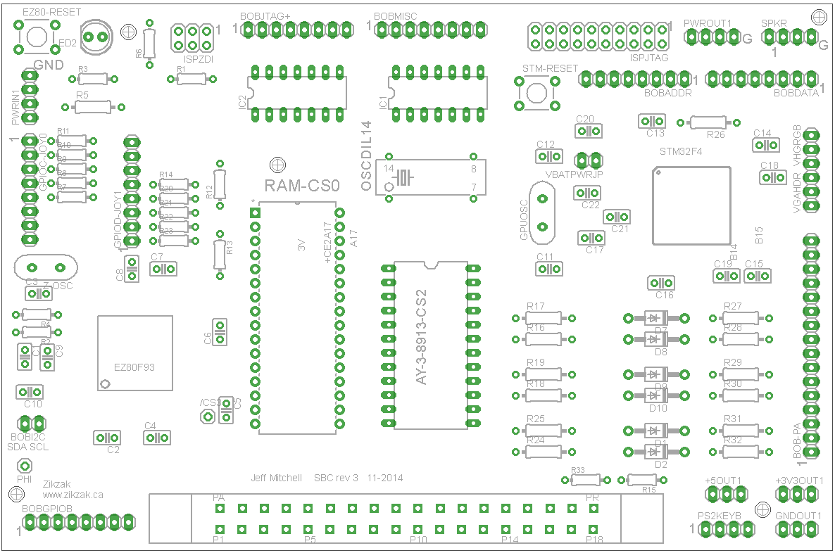
The up-side is I've got 8 custom jack parts made in my CAD library, which is probably all the custom parts I didn't have to make a shield or new PCB. EagleCAD sort of stinks in a lot of ways, so its a bit of a PITA to make the shield PCB (why can't you import an existing pcb layout and use it as a semi-visible layer, to make part placement easier for a shield..), but I can at least proceed on that. So next spare time step is figure out exactly what I'd like to put on there, and then arrange it. Doing the routing should be a hell of a lot easier than with the main PCB, since its not in the thousands of connections, so should route quickly once I nail down the inclusions.
The inclkusion list is complicated by such things as .. on the main PCB I didn't want to over-commit to a given purpose, so broke out some groups of pins multiple times; its expected you consult the schem/notes before populating it. ex: Like audio uses some of the same pins as one of the GPIO headers .. so you can use either the GPIO, or the audio, or be clever and use both (have the audio reset pin set while accessing GPIO, etc.) So, on the shield for example .. I'd like to have uSD slot (cause, could be fun to have access to files without resorting to putting them all on a cart, and putting an SD slot on a cart is a little goofy due to my cart pinout.) So, making a little mp3 player or mod player as a cart, with music files on SD.. why not? The SD slot isn't explicitly built into the ZZ main pcb, but using bitbanging or SPI pins gets you SD; but those pins are already used for option secon joystick. So, I should put the SD slot on there, and the pads for the second joystick, but not likely actually popualte a second joystick port. Its also got TTL serial which is very handy for console debugging from z80 to PC. So second joystick .. leave it off but present, but gai uSD and serial TTL... win! Or add the second joystick and lose the ability to use SD when waggling joystick?

I left some USB pins available from GPU as well in fact, to a BoB header; so could offer an actual USB host on the GPU, but the GPU is mostly acting.. as a GPU; still, its a general purpose microcontroller with full bus access, and could receive a 'hey, do some usb fun stuff' trigger from the z80, so could in fact write some code for the GPU to talk to USB devices like mouse or keyboard or fat disk storage or something. Crazy, but ZZ is all about the crazy right? So I should put a USB port on there, that you could populate or not. Call it 'data USB port'.
Then, another USB port say.. but one just for power, say. ie: So you could plug into the 'power usb port', to feed power from PC ito the ZZ; this implies putting a 5->3.3V converter into the shield. Why a second usb? Well, so you could plug usb into a PC for data but not power, or into thepower USB to supply power and still have the header available for non-usb stuff? I dunno, need to mull that over. Or maybe just commit to a single USB, that data pis are hooked up to the GPU and power pins supply power to the unit, that sounds pretty reasonable. But I also have a DC barrel jack header I use for normal powering the unit, so should offer that on the shield. But if you have a USB jack that can feed power, AND a barrel jack that can feed power, you're asking for letting the magic smoke out of a lot of stuff.. hence the idea of data USB jack and separate power USB.
JTAG (to flash the GPU) and zdi (flash the z80) could be on the shield, but they're already on the far side of the pcb; might as well leave those just on the main pcb, since you can fit the flashing cables in there anyway. But what if I want to put a 3d printed nice cast on the ZZ? that might make the flashing headers are to reach, so should I replicate them on the shield pcb, thus making most or all of the good stuff available right off the top? So a case just needs to be a box, with a bunch of port-holes on the top? Or better, put 90-degree pins for some of those headers, so the ports are on the back so it looks cool? I could populate a new ZZ pcb r3 pcb, and put all the un-shield ports out the back/sides, and have the shield ones be another layout out the back, or out the top..
.. its funny how you have to think software, and hardware, and then placement, and part availability/costing.. theres so many stratas to the design.
Personally, I'm sort of a fan of doing ZDI and JTAG and such as piouts out the back; cart slot of course out the top (cutout in the shield so it doesn't get in the way), and joystick or somethign out the front edge, be ice, ice and traditional. Problems arise due to spacing ... the existing ZZ r3 pcb puts things in more or less the right spot, but not if you're putting a shield; if ZZ r3 pcb has a joystick on the side, but you want to put a shield on for the real jack, well, the jack can't be in the same place, so the header from the base can come up to a female in the same place on the bottom of the shield, and then over to the jack that you place somewhere else nearby. So the shield adds real jacks, but in different locations.. hopefully better or as good, or meaningful.
So, thats why I started working on a rev4 .. put the jacks right on the main ZZ pcb; take away some of the features to make room (and tighten things up); ie: drop some headers, drop barrel jack and assume USB power, drop some redundancy etc... but thats a lot of routing work, and are expensive pcbs (like $70 for 10 or something.) Doing a shield might be cheap and easy and a godo way to prove a few things.. the incremental ("I'll get there, having fun doing it" approach).
So yeah, lots of decisions like those above to work out and once committed in my head, just lay it out and go. (or go back to rec4 and sigh, scary routing job

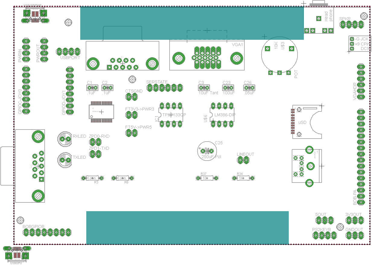
New jacks I put together (hopefully right, no guarantee

.. headphone, micro USB, barrel jack, PS/2 keyboard jack, POT wheel (volume control for the amp), Micro SD slot, joystick (Atari/Amiga style), and VGA.
jeff
edit; so yeah .. will be adding basic amp (lm386 or something) to the shield, for the headphone direct plug and play, including analog volume wheel.
USB and power conversion on pcb, instead of separate power pcb like I've done so far. The idea being.. the ZZ plus shield shoudl be a 'good to go' unit; plug in USB, plug in video, plug keyb or joystick, it can be useful. No needing to put on ports or use header pins or multi pcbs to bring life.
Another question is.. FTDI for ttl serial; right now I use a little ebay 'ftdi basic' clone, which is just an FTDI chip with ttl serial i/out on it, and a usb port; so you plug usb into the ftdi basic, and jumper the rx/sx pins to the ZZ, and now you've got console and power .. handy! The ftdi basic from ebay is cheaper than buying FTDI chips myself! (annoying!) .. its just s damned handy little pcb to have,m for all projects to get a quick serial console out of.
But maybe I should add the FTDI chip onto the ZZ shield direct, to get console? but thats yet another power point option

(another usb -> power option)
i2c is available off the ZZ base pcb; do I expose those on the shield, or just let people go direct to ZZ main pcb; no point in exposing every possible option on the shield.. just gets cumbersome then.... or maybe its good; ppl don't have ot popualte every pad, but maybe nice to replicate them all there. Also means less risk.. hack away at the shield, without risking wreckig the much more complex/pricey main pcb...
 .. anyway, heres to hoping RL slacks off a bit so I can get this latest iteration of zikzak done goodness, time flies!
 )
)


