Zikzak - crummiest 8bit console/computer ever .. but I'm making it!


Wow, work really blew me away the last few months; I'd hoped to hammer through some fun stuff through end of December but RL affords no time when you want it. (What do they say.. the things you do while procrastinating, is what you really should be doing.. ;) .. anyway, heres to hoping RL slacks off a bit so I can get this latest iteration of zikzak done goodness, time flies!

(Also, I want to work out another iteration of one of my quadcopters, and get some FPV (first person) flying/video done through the winter.. though I did a quick clip of flying by my Christmas lights at night, if anyone caes :p)

jeff
 
House lights from a roflcopter? Sign me up; do you have a yt account?

And yeah, I generally get nothing done in december every year. Family commitments and everything else xmas flavoured mean not much gets done.
 
Here is my Christmas lights flyby in slowmo (sorry, no music/sound):

You can find other random videos from over the years there, mostly electronics hacking stuff :)
 
Rather than an expansion 'shield' to add SD to the zz, I'm thinking of putting it right on there; and a real USB, not just a USB header.. but that implies possibly charging/powering by USB so maybe needing the whole power bits on the main pcb ..

Real life work is too nuts (layoffs, working around the clock etc) for quite awhile.. really getting in the way of this fun stuff!

Just waiting for some more parts to show up while RL kicks my tail...
 
okay, as noted in the C64 thread, I've been working on and off on Zikzak ("ZZ") again; the last couple years continue to limit free time (kids will do that, and work laying people off, moving people around, being bought, etc and so on..), but I'm still hacking. Born to hack :)

The last real ZZ board was rev3 ("r3") which was pretty solid; it still assumed an off-board DC power board, and off-board amp if needed, and off-board serial FTDI if you wanted one, but otherwise was complete on board; lots of pin-headers for everything (i2c, SPI, joysticks, ps/2 keyboard, audio raw, you name it). It worked. Video, audio, joysticks, keyboard, RAM, ROM, all of it. The audio probably has some glitches, but I'm not sure yet .. it passes basic tests, but I was never one for audio or chiptune coding, so I've not written up any useful music. I can play basic gunshot sounds and some very basic 'music' (note tables), so its more or less right, but I worry if theres not some funny business. Or it could just be spotty parts from ebay, since getting the retro sound chip is increasingly hard (very old stock, pricey, etc.)

My plan for rev4 was to put the real connectors on the board in addition to (or in place of) pin headers.. That needs more space, but I'd already gone to a 4"x6" pcb (pricey but a good size), but that ight not have the room I'd need. it'd certainly be a total re-route of all the wires, which would take a couple weeks of hard work. I didn't super cram everything in, like to leave it laid out logically and nicely, allowing for a bit of air around sections and parts (always good when you're not entirely sure what size actual components will be later etc..); I'm suing mostly through-hole parts where convenient, since they're easier to work with by far than surface mount.

I ended up just not having a tonne of time to do that, so waffled back to the idea of a shield/cape .. an add on break-out board; I multi-purpose a lot of pins so it may be hard to do cleanly, but at any rate.. why not take the header pins on r3 (I have 10 of those pcbs after all!), and put longer pins on them up to a shield; so where the joystick/serial pins come out for joy0, just pass them straight up long pins to a add-on pcb; that pcb could in turn move over a bit, and expose the original pins, as well as a joystick connector jack. By doing it on a separate pcb that just sits on top (or below) the original, you get all that space to work with, so can break-out like crazy. If laid out well, it might even make it for case design easier.

(Mind you, the r3 design was intended to itself go into a case with jumpers to connectors; that turned out to be poor idea, since printing a case and screwing connectors onto it makes it al very weak and crack-y.) So r3 has all these connector headers around the periphery, where I effectively actually want real connectors. So if I send them up/down to a BoB, you can't easily put the connectors in the same place around its periphery.. since you have to solder there for the bridging headers instead So, I'll have to put connectors all over the edges or middle of the BoB, so that'll be a project for some paper and cutouts, sliding things around to see what would make sense (if anything.)

Worst case is to go back and work at rev4, but using this existing shield exercise as a driver to force me to measure all the parts out and design up all the connectors and make a zikzak-library; once all those parts are in place, I can proceed whatever road

In doing a Bob, it is also tempting to overload it .. for sure bring the audio amp onto it, and maybe even the power circuit. The power stuff is goofy, and hence separate pcb, since you can power from USB, or from a battery, or from DC wall wort, or etc. If I move it to BoB, then I'll probably still have a USB input which could be USB data, or usB for power; but I do like to power from other sources, such as a FTDI serial->PC (logging etc), or from a barrel jack. So, hence, keeping power off so the main zikzak boards are simple. In one of my other experiment boards, I made a USB-or-barrel power thing, where you'd only solder in one set of components, or maybe had a switch (I forget), so it could at leat be configured different ways, but that's all sort of dorky

... anyway, another point of thought for a possible rev 4 is audio.

I'm still using the AY-3-8910 (and variations, like AY-3-8912 etc) for audio; its a classic chip, sounds great. There is also the YM2149 the Atari ST used, which is bascly the same chip but with higher resolution audio. But all of these are getting rare and costly. I've got maybe 12 or 13 of these chips on tap (I tried to have enough random ebay parts to make 20 zikzaks.. but if I ever went to make a few hundred of the, I'd have to go buying a pile of parts and redo the parts libraries in the CAD, but that's a whole other adventure in designing for production.) Still .. it is tempting to put a cheap atmega on there instead of the big old AY-3-891x, and have it simulate a SID chip (fun!) ......

... or maybe just get the space back and have the ez80 drive audio, or the STM32 GPU. Using those is sort of tricky though ... since I put articirficial painful limits on myself to avoid 'cheating', and ease of soldering.. (no surface mount chips with 160+ pins etc). So the bus between STM32 and eZ80 is pretty busy, and I have it so the STM32 is master; its rendering video which _Cannot_ be delayed without causing glitching, so the z80 cannot pause the bus; the stm32 is in a tight rendering loop, and when it wants data from the RAM/ROM bus, it essentially pauses the z80. In the past, the machines ran a double clock (say, 16mhz) and then had each part running at half of that interlaced, say. But I can't really get away with that, due to VGA. On the upside, since I'm making my own protocol, I got away with some tricks.. the z80 can inform the stm32 when theres a new frame (change in memory), and the stm32 can let the z80 know a few things. They can communicate different concepts back.. so the z80 can inform the stm32 that video is in RLE or in sprite-map or in raw-pixel-framebuffers or sprite-lists or whatever.. so it can use much less memory to describe a text screen than a full bitmapped graohic screen. Less data to detail a screen means less time for stm32 to read the bus, and therefore the z80 can run more %age of the time. Its a dorky design, but very easy to understand and hack around. But as a side effect, I'm not sure either chip is great for controlling audio, which is why I offloaded audio to a third chip _anyway_...

Decisions decisions.

Anyway, sorry for the ramble, but a few delightful people here got me revved up, so here I am spamming the boards again with my experiments :)

Also, my old bench power supply was driving me batty and killing parts. So for my tax return and last work bonus from my old company before it was bought, I bought a shiny new power supply. I've got a serious little electronics lab in my basement :)
 
Barrel jacks are getting pretty retro already - sure you want one of those? USB power should be fine for most users, battery headers for everyone else who wants to put it in some random old handheld case, as seems to be the trend these days. And I'm personally a fan of anything you can power with croc clips, so + and - pads like on the pandora across the middle might be good for when I'm having a Dr Frankenstein moment.

Old Amstrads and BBC micros are probably still ten a penny over here - not sure what else had an AY chip over your side of the pond.
 
The reason for the barrel jack, was so I could take in random power (say, 7-20V) and bring it down to the voltages I need (such as 5 and 3.3); when you do that (aside from bleeding off heat or ripple), you generally get a pretty consistent voltage out. If you just assume the input is 5V, that probably more or less works (USB shoudl be pretty good), but you do open yourself up to crappy USB DC-DC wall worts or lame supplies. But I suppose in my case I could just put in a assumption 37: Your USB input is standard, solid, and can handle X mA" or something :) In that case, with a 5V input from USB, I could run it through TI 7133 to get a 3.3V output (up to a little less than 2A!) .. which is what the z80 and stm32 run on anyway, so that'd be pretty reliable. The 5V would be for audio and such so I guess a bit of flakiness could be tolerated. I think most boards will allow 500ma to 900mA on a USB port, so that should be sufficient most of the time.

In my power bus I tend to pass around the Vsupply plus the 5V, 3.3V and GND; though in truth, I think I only pass the 5V and 3.3V to the cart, not the Vsupply, so maybe its moot; Originally I intended to pass along the full voltage rail to the cart, just in case someone wanted to have a big wall wort and do some crazy businewss in the cart.(The cart essentially has full access on the bus, so you could do some fun stuff in there.)

There is always the ZZslim idea, and drop all the extra stuff; drop cart slot in favour of SD, drop fancy audio, drop second joystick, etc, etc; make a 4" square pcb that does a lot less, but all the main stuff most people care about anyway. But thats no fun, so not somethign I'd worry about unless some other model 'takes off' first.

One old idea is to port the arduino core libraries over to the z80, so that a bunch of random arduino code could build out of the box; that lets you adopt some of that large userbase, or make it at least easier for people to jump over. But then, with arduinp or r-pi, theres not much one can offer them.. they can get FPGA VGA shields, etc and so on already. The ZZ's angle is the build it up yourself, learn how to make a computer/console, mod like crazy :) .. not make robots with it, per se. (though, natch, I have done).

So, while thrashing around in the head to determine a real direction, I'll keep on the current one; its amusing, and something I can bite off in spare time, and leads to thinking about things so a future direction can hopefully become more clear.

jeff
[doublepost=1462330334,1462330028][/doublepost]I need to dig out a Speccy emu or something, and figure it out just enough to code a very basic music demo; then port the same code to zikzak, and compare. Need some way to 'prove' if the zikzak audio is working. I suppose by extension, I need ro get a known good AY-3-8913 ... I've had people tell me that when they bought them off ebay, the noise generator was broken etc, that all the ones on ebay are from the bad yields, etc. They seem to work in every way, but the anlog audio out is flaky, etc. I'm not a audio nerd, so I tend to just assume my board is bad, but too much surface area to check all at once.

Perhaps I should wire an AY-3-8913 up to an atmega, and do direct testing there (again.) I did that long ago, used it to prove it enough in my head to make the ZZ design for it; but the way the ZZ talks to the AY is a little goofy due to the bus sharing and so on, so its possible the high speed switchign on the bus is confusing the AY, so I keep meaning to prove if it works better or differently if isolated or not. I've also heard tell of bugs in some of the AY chips, where you need to drop it to reset in certain cases (ie: that when it powers up it is not itself properly reset.. so you need to power it up, wait, and then reset it, and then drive it... whereas I just assume its reset on power up.) Etc...

Hmrf. Audio, always the fang in my side :) From hacking arcade boards, to writing emus, to building hardware.. always audio is a pita for me :)
 
(carrying on from other thread)

rygD ..
I would be interested in messing around with one. I don't know what would be the best fix for some of the problems you would run into making it more of a product, and I don't have time to think about it atm. I will probably check out your thread and blog again later, and join the conversation (i just always feel like I am in way over my head)

I've probably got 8 or 9 of the ZZ r3 bare pcbs around, and a few of each of the components (ie: cart edge connector, resistors, stm32, ez80, etc.) The ez80 and stm32 are tricky to solder (surface mount, high density) so I could solder those for you (though its hard to test if they're successfully done without also doing up a lot of other things, like capacitors at least.) If I ever went mainstream then I'd have them at least pre-populated, but this is all roll-your-own stuff :)

Offer stands.. anyone who wants a ZZ r3 kit, I can put together a little package for you, with varying degrees of assembly/testing depending on your experience/comfort level.

Note; you have to accept that its beta level hardware, with almost no useful firmware; its all roll your own. I've got lots of dumb little demos, but its not like you can just pop in a cart and play space invaders.. gotta write space invaders first :)

So yes, I'll work on a BoB shield for r3, which will then offer up convenient jacks instead of header pins, and then try to settle down the firmware and maybe make up a simple space invaders game or something, so that it actually has a simple pug and play with demo cart going on. That might be the time for me to pack up a few for people, so it can arrive and be assembled and actually do something semi useful :)

jeff
 
Stupid little things, but here you go..

I have 10 headphone jacks (female pcb side); unknown pinout to start with. Had them lieing around for 3 years or so, random vendor. Audio has always been my weak side, so I don't know a lot, or any of the standards, etc. I do know all you need is gnd and a + to get audio, but as to whats going o, not my speciality :)

So, these guys have 11pins, so.. yike! Normally for a jack, you can connect up the other side (think VGA say) and run some continuity tests and voila work out a pinout (or google them, of course); most jacks are fairly exposed on male and female sides. A headphone jack is not so easy .. the female side is enclosed, with a few little switches in there; but how it coudl work out to be 11 pins eluded me... and getting the male ed is sort of annoying. ie: Get an old earbud you hate, cut the wires, and .. they're very tiny, hair width and twisted all to hell, so sort of hard to work with.

So, that was the first couple minutes.

Looking at it under a magnifier, realized its actually two blocks stuck together; without much effort was able to pry them apart, and had a 5pin block including the actual female recepticle, and a 6p header, with a spring switch on the inner-surface. Doesn't seem to be any signalling contacts etween the two blocks, and while attached an insertion/removal didn't seem to toggle continuity across the 6p .. I had sort of assumed maybe they are just for stress releief (strength to pcb) and/or provided a insertion validation check (ie: pull-down on insertion, or something.) Well, no idea in those few seconds but it didn't seem overly useful, so put it aside. Who cares?

Measuring the spacing on the remaining 5 pins and they're all .1" standard through-hole, which is nice. (some spacing between pins, but whatever.)

Insertion/removal of a headphone male side, and beep test, shows that its:
1 pin .... row 1 -> GND
4 pin .... row 2 -> 2p pair + 2p pair

ie: the two pairs are contact switches.. so once inserted, the 2 pair become Open (normally closed.) .. I guess thats your insertion test.

So now we're down to gnd, Left, and Right.

Its still hard to determine which is left vs right, since you can't hook an extra wire onto that male end to do testing with; but maybe I can stick it partly in and see if one of the pairs contacts opens before the other, to see which is first in line. A standard headphone is "TRS" (tip, Ring, Sleeve), while the mic laden ones are TRRS (tip, ring, ring, sleeve). In this case, just stereo, its TRS, so you know the sleeve (furthest back) is gnd; tip is Left, middle ring is right. So, wordt case is you lay out your pcb at random and swap left/rights (oops!), but should hbe able to work it out with some probing.

I'll probably just do mono audio ANYWAY so, why worry?

Anyway, always nice when a 5 minute bit of probing details everything :) Got spacing, reduced part size, sorted out enough info.. good to go, no worries :)
 
<brain dump mode>

Didn't work it out yet, and as it seemed a non-useufl extra block, haven't pursued it. I don't have a handy TRRS male on my benchtop, but maybe those are longer and protrude into the 6p block; or perhaps theres some custom connector that goes in there, or something. No idea where I got these from :) I originally thought they'd be pin duplicators .. to get a nice 2x3 grid of simple pins to work with instead of the sort of odd arrangement the fornt block has. But who would exchange pcb layout space for 'convenience', when the existing pinout is plenty-fine? So, yeah, no clue offhand, but I'm sure it makes sense in some context.

The up-side is I've got 8 custom jack parts made in my CAD library, which is probably all the custom parts I didn't have to make a shield or new PCB. EagleCAD sort of stinks in a lot of ways, so its a bit of a PITA to make the shield PCB (why can't you import an existing pcb layout and use it as a semi-visible layer, to make part placement easier for a shield..), but I can at least proceed on that. So next spare time step is figure out exactly what I'd like to put on there, and then arrange it. Doing the routing should be a hell of a lot easier than with the main PCB, since its not in the thousands of connections, so should route quickly once I nail down the inclusions.

The inclkusion list is complicated by such things as .. on the main PCB I didn't want to over-commit to a given purpose, so broke out some groups of pins multiple times; its expected you consult the schem/notes before populating it. ex: Like audio uses some of the same pins as one of the GPIO headers .. so you can use either the GPIO, or the audio, or be clever and use both (have the audio reset pin set while accessing GPIO, etc.) So, on the shield for example .. I'd like to have uSD slot (cause, could be fun to have access to files without resorting to putting them all on a cart, and putting an SD slot on a cart is a little goofy due to my cart pinout.) So, making a little mp3 player or mod player as a cart, with music files on SD.. why not? The SD slot isn't explicitly built into the ZZ main pcb, but using bitbanging or SPI pins gets you SD; but those pins are already used for option secon joystick. So, I should put the SD slot on there, and the pads for the second joystick, but not likely actually popualte a second joystick port. Its also got TTL serial which is very handy for console debugging from z80 to PC. So second joystick .. leave it off but present, but gai uSD and serial TTL... win! Or add the second joystick and lose the ability to use SD when waggling joystick? :)

I left some USB pins available from GPU as well in fact, to a BoB header; so could offer an actual USB host on the GPU, but the GPU is mostly acting.. as a GPU; still, its a general purpose microcontroller with full bus access, and could receive a 'hey, do some usb fun stuff' trigger from the z80, so could in fact write some code for the GPU to talk to USB devices like mouse or keyboard or fat disk storage or something. Crazy, but ZZ is all about the crazy right? So I should put a USB port on there, that you could populate or not. Call it 'data USB port'.

Then, another USB port say.. but one just for power, say. ie: So you could plug into the 'power usb port', to feed power from PC ito the ZZ; this implies putting a 5->3.3V converter into the shield. Why a second usb? Well, so you could plug usb into a PC for data but not power, or into thepower USB to supply power and still have the header available for non-usb stuff? I dunno, need to mull that over. Or maybe just commit to a single USB, that data pis are hooked up to the GPU and power pins supply power to the unit, that sounds pretty reasonable. But I also have a DC barrel jack header I use for normal powering the unit, so should offer that on the shield. But if you have a USB jack that can feed power, AND a barrel jack that can feed power, you're asking for letting the magic smoke out of a lot of stuff.. hence the idea of data USB jack and separate power USB.

JTAG (to flash the GPU) and zdi (flash the z80) could be on the shield, but they're already on the far side of the pcb; might as well leave those just on the main pcb, since you can fit the flashing cables in there anyway. But what if I want to put a 3d printed nice cast on the ZZ? that might make the flashing headers are to reach, so should I replicate them on the shield pcb, thus making most or all of the good stuff available right off the top? So a case just needs to be a box, with a bunch of port-holes on the top? Or better, put 90-degree pins for some of those headers, so the ports are on the back so it looks cool? I could populate a new ZZ pcb r3 pcb, and put all the un-shield ports out the back/sides, and have the shield ones be another layout out the back, or out the top..

.. its funny how you have to think software, and hardware, and then placement, and part availability/costing.. theres so many stratas to the design.

Personally, I'm sort of a fan of doing ZDI and JTAG and such as piouts out the back; cart slot of course out the top (cutout in the shield so it doesn't get in the way), and joystick or somethign out the front edge, be ice, ice and traditional. Problems arise due to spacing ... the existing ZZ r3 pcb puts things in more or less the right spot, but not if you're putting a shield; if ZZ r3 pcb has a joystick on the side, but you want to put a shield on for the real jack, well, the jack can't be in the same place, so the header from the base can come up to a female in the same place on the bottom of the shield, and then over to the jack that you place somewhere else nearby. So the shield adds real jacks, but in different locations.. hopefully better or as good, or meaningful.

So, thats why I started working on a rev4 .. put the jacks right on the main ZZ pcb; take away some of the features to make room (and tighten things up); ie: drop some headers, drop barrel jack and assume USB power, drop some redundancy etc... but thats a lot of routing work, and are expensive pcbs (like $70 for 10 or something.) Doing a shield might be cheap and easy and a godo way to prove a few things.. the incremental ("I'll get there, having fun doing it" approach).

So yeah, lots of decisions like those above to work out and once committed in my head, just lay it out and go. (or go back to rec4 and sigh, scary routing job :)

New jacks I put together (hopefully right, no guarantee ;) .. headphone, micro USB, barrel jack, PS/2 keyboard jack, POT wheel (volume control for the amp), Micro SD slot, joystick (Atari/Amiga style), and VGA.

jeff

edit; so yeah .. will be adding basic amp (lm386 or something) to the shield, for the headphone direct plug and play, including analog volume wheel.

USB and power conversion on pcb, instead of separate power pcb like I've done so far. The idea being.. the ZZ plus shield shoudl be a 'good to go' unit; plug in USB, plug in video, plug keyb or joystick, it can be useful. No needing to put on ports or use header pins or multi pcbs to bring life.

Another question is.. FTDI for ttl serial; right now I use a little ebay 'ftdi basic' clone, which is just an FTDI chip with ttl serial i/out on it, and a usb port; so you plug usb into the ftdi basic, and jumper the rx/sx pins to the ZZ, and now you've got console and power .. handy! The ftdi basic from ebay is cheaper than buying FTDI chips myself! (annoying!) .. its just s damned handy little pcb to have,m for all projects to get a quick serial console out of.

But maybe I should add the FTDI chip onto the ZZ shield direct, to get console? but thats yet another power point option :) (another usb -> power option)

i2c is available off the ZZ base pcb; do I expose those on the shield, or just let people go direct to ZZ main pcb; no point in exposing every possible option on the shield.. just gets cumbersome then.... or maybe its good; ppl don't have ot popualte every pad, but maybe nice to replicate them all there. Also means less risk.. hack away at the shield, without risking wreckig the much more complex/pricey main pcb...
 
Last edited:
Brainstorm in a moment of free time.

So ZZ r3 pcb just has a power-header (for input) and it replicates them to a bunch of header pins on out-side (for jumping over to things like to GND out a pin, or pull up a pin, etc. They're just handy to chain, so I have output voltage pins)

So, the way I usually power r3 on my bench is..
- power supply -> optional regulator (depending ho wreliable the PSU is) -> header pins
- DC barrel jack from wall wort -> header pins
- USB -> regulator pcb (I made a little power supply pcb years ago) -> header pins
- FTDI Basic mini board, which takes USB 5v and spits out 3.3V and does the USD<->serial-TTL so the mcu can talk to a PC over USB, and show up as serial port

As you see, I like having options :) I put only power in pins on the ZZ r3, so that the power complications (all these options, plus worrying over ripple etc) on another boar;d I sort of envisioned at the time a larger cased unit, like an Atari 2600 junior sort of form factor, so would have plenty of space. These days I'm more thinking of a small brick form .. like say 7"x4" sort of form. Anyway.

I'm okay reducing options on the shield, since its all just for fun, and the ZZ r3 base pcb still has all the options.. and if the main use case would be the one covered. Like, if theres a lot of useless options, its okay to ignore them for now. (In an ideal world, I'd just go for r4 and reorganize the main pcb and put jacks on and all that, but I'm having fun with the idea of a shield right now. So we'll see if I can CAD a shield all up, and then see about actually making them or not, or going for r4 or not, etc.)

So, a shield would probably replicate the power in pins, just because.. its nearly free, and gives options.
- DC barrel jack .. I could put the pins for it (3 small pins) on ther,e and just not populate it . but putting them on there implies DC-DC regulation; you can't assume a wort is reliable or ripple free, so typically you' want a higher voltage wort than you need and regulate down to get the right and clean voltage; if we drop the barrel jack, it means no need for DC DC regulation.. so save a chip possibly. ie: the TPS7133QD X->5v
- USB for power.. well, if we take USB (5V), we'd need the TPS7133 chip anyway to get us 3.3V; so maybe rough in barrel jack works, since powering via USB makes a lot of sense
- but, if I include an FTDI what was it.. 232 chip, that can do the serial USB magic, and also inherently regulates out a 3.3V rail from the USB 5v line.

So, one would think ..
- header pins for power in, with a jumper to enable/disable them
- include FTDI and uUSB port, and voila .. you can do powering + serial over USB
(and still have a data usb uUSB port for the gpu to talk data USB, ignoring its 5v and GND lines)

But if you wanted to demo something without a PC nearby .. would you want a barrel jack, or just use a wall wort USB brick and jack in that way? Probably the latter. Devices today are often powered like that. (ie: Raspberry pi, for example..)

In ZZ r3, the second joystick shares the serial I/O pins for the z80 side (not the stm32 gpu side). So if we just assume the FTDI is present for serial, then we sort of just lose the second joystick and gain a few more IO pins for general use.

Another option I suppose is jumpers .. FTDI serial going to rx and tx pairs of pins, so you could put a little jumper-short across the pins to enable FTDI serial to work, or take it off to break it; this would let you have joystick 2 or not. (For something like ZZ which is just hacking around, do we actually need joy2? We could just support it on the ZZ base pcb, but ignore it on the shield, since the shields goal is to simplify and make the unit sort of usable, easily.

ie: With the shield, you just pkug in power (say, USB) and its alive; add VGA and a joystick to get basic gaming, or VGA and a keyboard to get a computer, or whatever. Speakers or headphones into the headphone jack to get audio, etc..

Nice and easy.

So.. is second joystick something worth keeping on a goofy project like this? If so, probably could, just a couple header pins for jumper-to-enable or not. (or maybe I should add a little toggle switch though that gets goofy.)

IF we ever went with a shield, and people actually wanted it, then they would probably know the kind of person the are .. by default, seiral disabled and two joysticks work; a dev head would jumper the serial and lose the second joystick, so he could use serial for console/debug/flashing/etc.

yeah, I think I'm liking this. USB for power and serial, lose focus on the DC barrel jack.

jeff
 
That USB chip sounds magic. It regulates out 3.3V and does serial? I guess 5V to 3.3V is only 1.7V, and if you're only taking a few hundred mA through it, that's less than half a watt of heat to be burned off, but I'd still count that on the toasty side assuming it's a small ceramic doodad.

Second joystick port is definitely worth keeping by default if this ever goes public. Like you say, devheads can install a jumper to make it do serial instead if they want, assuming it's documented somewhere handy (like, printed on the board, perhaps).
 
yeah the FTDI chip is great; its what made arduino popular .. arduino is really just atmega + ftdi + bootloader, and some software.., plus the passives. Having USB to flash or serial log is insanely handy, and it does the 3.3V rail for you. And due to arduino popularity, those chips are crazy easily gotten at good prices. Hell, I ordered a 10 pack from ebay (China) .. who knows if they're couterfeit or what, but they do the job! I basicly decided you have to have them on every pcb with an mcu.. serial logging over usb is absolutely essential.

jeff
 
So.. is second joystick something worth keeping on a goofy project like this? If so, probably could, just a couple header pins for jumper-to-enable or not. (or maybe I should add a little toggle switch though that gets goofy.)
Getting goofy on a goofy project seems somehow appropriate. ;)
I say go the toggle switch, that way someone can decide what type of machine they need on the fly. :)

-Neelix
 
Question is, make it one of those massive (but probably still sub-miniature) metal level switches, after 1970s wire wrap machines, or DIP switches, after 80s arcade boards?
 
FWIW.. did a quickish test tonight.

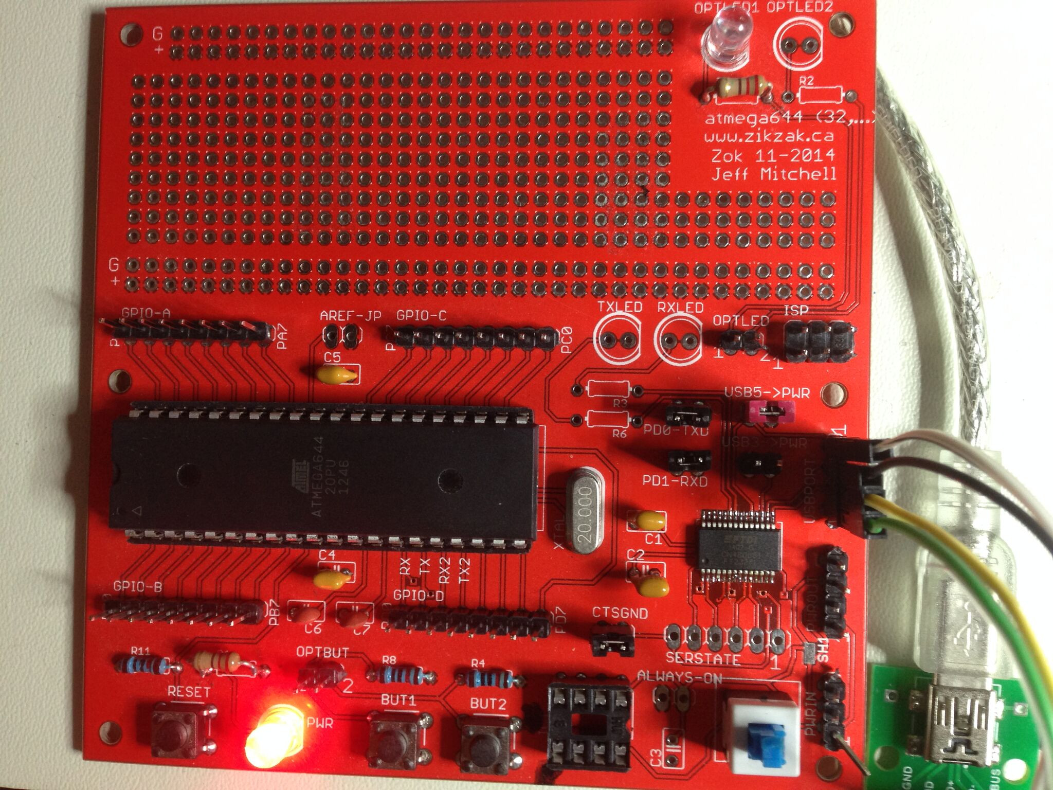
One of my little test PCBs is 'Zok' (Zik, Zok, you got it.) .. the Zok is just a handy little prototyping board for atmega644 (or similar) .. one of my preferred mcu's for hacking around. Essentially, Zok is compatable to an arduino, but its my own design, and in many ways more flexible (at least, more configurable.) ie: you can power it from header pins or USB (FTDI chip here); so you can populate that or not. It has jumpers to enable FTDI for serial (or just leave the atmega pin headers for serial); it can use a jumper to pick up 5V or 3.3V from the FTDI, or not. Put a jumper on to enable a LED or two for whatever you like (hearbeat tests); it has a power toggle switch, reset button, couple optional buttons you can jumper to enable, space for a clock crystal, and all the breakout pins. In short, you can just drop an atmega chip on there, add two or three caps, and it'll run. Want some BoB pins, its all there, just solder them on. Want serial, solder em out; want FTDI, solder it on. Arduino sort of comes 'with the works', but I like to be minimal, assume nothing.. o wasted interupts, power, etc.

Anyway, I put Zok together a year or two back, and used it to drive one of my car-bot experiments; just threw it on as another pcb while having ZZ r3 (or something) etched .. for $10 more, why not throw on any pcb? (so, got 10 or 15 Zok pcbs around if anyone wants :)

I'd never gotten around to testing the FTDI bit of the Zok; didn't need it. Well, did it tonight, so I can copy/pasta the FTDI schematic part from Zok to ZZ r4 and/or r3-shield.

Fortunately, it all works just-right :) Those FTDI chips are easy to work with. Solder the FT232RL onto the Zok, 2 caps (decoupling the 3.3V and 5V lines out), and its live. For Zok, just added the 5 jumper pairs to enable/disable features (serial enable or not, etc), and wrote a little teeny avr C program to toggle a LED and spit messages out over serial->USB via FTDI.. works a treat.

So, now ZZ will have USB for optional serial, and for powering. Seems a good thig to do on the shield, and all the other power options are still on the rev3 ZZ main pcb of course.

jeff
[doublepost=1463027498,1463026818][/doublepost]Image of Zok pcb, populated, with FTDI on lower right side (the surface mount teeny chip)
zok-populated-ftdi-test-002.jpg
 
As expected, its challenging in the placement sense, to make the shield. I've not even started worrying about placement, relative to putting on a 3d printer case yet, but just trying to place things 'at all' Will post a screenshot of the CAD pcb layout so far when I get a moment (I post these little blurb braindumps while putting little kids down for bed .. after reading and drinks and pee and all that, hang around a few mins till they pass out...)

So, the Zikzak r3 pcb was laid out to go in a case, with header pins via jumper wires to the jacks; that didn't work out (not enough strength in case to hold up a jack without also being soldered down, and jumper wires all over are fiddly and annoying. Also, when you're just using the pcb on a bench like I do, jumpers after awhile are just sloppy.) So, anyway, the ZZ r3 pcb has the header pins all around the periphery, which made sense at the time, but really sucks for adding a shield. Ideally in a shield/cape/whatever-you-call-it expansion BoB board, you want all the connections in the middle (say), or in clusters, so that you minimize the space wasted by that bridging and maximize the periphery space for actual good stuff like jacks, screws, supports, etc. In my case its the reverse.. the shield layer has most free space in the middle, and most of the periphery is already wasted. ie: since ZZr3 pcb has header pins around the outside, if you picture two layers atop each other with the long header pin bridge going from bottom to top .. the top layer (shield) also needs header pins (female, say) to receive the bridge.. so that space is wasted.

VGA, joystick ports... very very big. Like, enormous. Then stuff like SD slot should be on the periphery edge... but just no space. Thumbwheel for volume .. should be on outside edge but not likely any space. USB jacks must be on outside edge, as they rather depend on open air for the male end to be. PS/2 keyboard connector should be edge, but actually fits in the middle okay, if there space for the male cable part to lurk (no ICs in the way.)

One annoyance is the cart slot is on the edge, taking up pretty much a whole side, and theres not much you can do there; I could mill (cut) out a big spacer around it (have to anyway, but _moreso_), and that sort of manufactures an edge that's available when no cart is in place. ie: could yank the cart, put in SD, adjust volume, then put in cart, say. Dorky, but does the job. Also, a prime use-case of ZZ is with no cart of course, just talking serial to it or flashing it, etc. (It has some small storage even without a cart.)

The other side opposite the cart has potential; it has JTAG and ZDI for flashing the two main chips, but those headers can remain on the main pcb; so the shield could just go right over top of them, or have a cutout to ensure they're available.. but either way, has a big edge, enough for a jack or two or so.

So, really, the ZZr4 idea is still best, cram it all in there, but I'm no sure I could fit it all in a 6"x4" pcb, with through hole parts. This is why all modern boards are surface mount.. double the surface area outright in a way, and the parts are all tiny.. modern hdmi half the size of VGA and includes audio, for instance. Still, that's not our game. Putting a ZZr3, into an r4 approach with jacks is already looking rough, but it also has to have some more DC power and an audio amp squished in there to be feasible. That's why 1980s consoels were all huge, but I don't want to go past 6"x4" (pricey enough already!)

So, will keep going for a shield approach, just as a good test for everything.. get the schematic down and etch a few pcbs, and try it out; that'll prove the schematic at relatively minimal cost (no need to make new ZZ parts, just clip it onto existing ZZr3 hand populated pcb). If in the end we need to go for ZZr4 and all in, super tight pcb, well, at least it'll all be proven parts libraries and all that by then. Incremental steps.

I'll post pcb layout for r3 and shield in a bit, so you can see where I'm coming from, where I'm trying to squeeze it all in.

jeff
[doublepost=1463189782,1463189713][/doublepost]And oh yeah the shield also has new functionality .. the SD slot, the two USB OTG jacks (one for power and serial to PC, the other as pure OTG client, so zz could emulate a mass storage or human interface device, etc.) Lost cramming in there :)
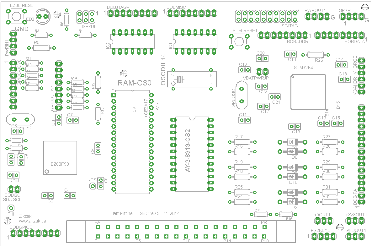
[doublepost=1463190815][/doublepost]PCB layout (pads, drills, edges only .. not wiring/etc) of zikzak r3:
zzr3-just-pads-etc.png

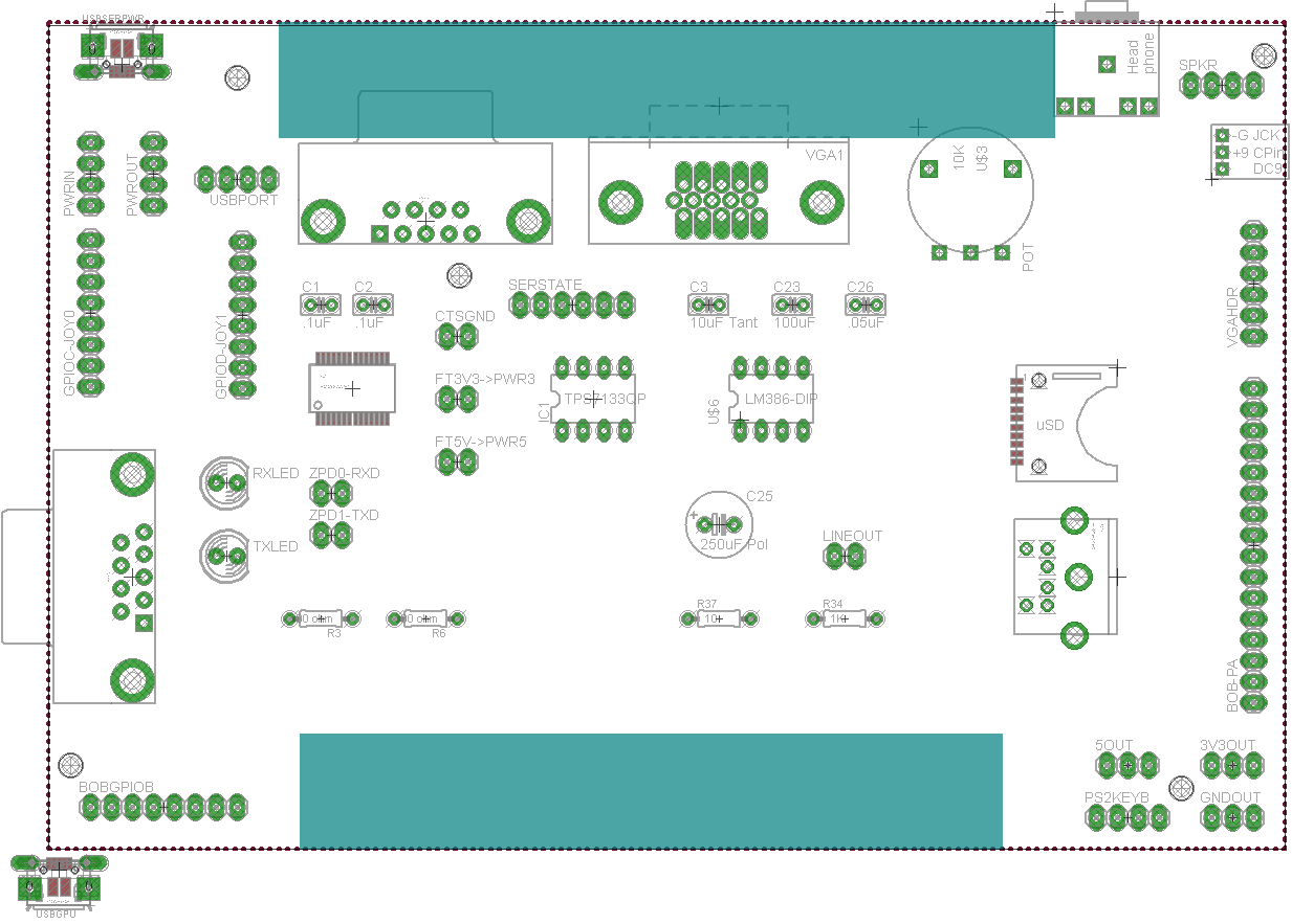
The zzr3-shield-r1 WIP so far (ie: certainly not anywhere final layout) is here..
- the blue bar top/bottom edges are thinking about cutouts.. bottom to make room for cart slot, top just to manufacture an edge for jacks, while giving room for ISP and ZDI .. though I will measure and see if that top cutout is even necessary at all

zzr3-shield-r1-layout-wip-001.png
- the uUSB jack at the bottom is not placed at all yet (ie: outside the pcb); this is because I need to juggle things around to find a place

So you see.. all those lines of pads are from the zz r3 header pins, and most of the outside edge is already consumed.

I could just ignore some.. like that big one on the right, the GPU PA "BOB PA" header; could just not bring that up to the shield at all, and have a big edge there for say two joystick ports. But that PA set of pins is useful for random stuff (including serial TTL from the gpu, in case we need to log something from there, or talk directly to it; I've done that, to control demos or change video modes etc, without going through the z80 over the bus to it.. .. like a GPU debugger console, how cool is that?) .. but mainly, that's where a second USB port hooks up, what I call the 'data usb' or 'gpu usb'; the z80 has no native USB support; the first uUSB on the top edge is mainly for power, or serial console from z80 back to the PC, via the FTDI chip. The data USB is something could just skip, or populate it and do crazy stuff with; the STM32F4 that I use for GPU, has a built in USB controller, so .. could code up a mass storage mode for USB, and then have the z80 tell the gpu to open or close USB mass storage or whatever ... like, could have zikzak act as a keyboard or mouse or touchscreen or whatever for a PC; we never will, but when did I ever let that stop me?

So, this is not even all the breakout that the ZZr3 offers.. like i2c; its already offered by the base board as pin headers, so theres just no point in bridging it up to the shield, where it would just stay as pin headers the shield is to make life easier, turn pinheaders into jacks, and include the audio amp and some DC and FTDI stuff. So, ZZ r3 is quite flexible, but we're really fleshing it out with the shield...

jeff
 
If you did end up going to r4 is there any reason not to stick with a two board design? Make r4 a simple rearrangement of r3 to put the headers in more convenient locations then you'd have more freedom in laying out the shield, and you wouldn't have to worry about making the PCBs too cramped.

Just a thought...

-Neelix
 
Back
Top