Zikzak - crummiest 8bit console/computer ever .. but I'm making it!


Firstly, I think we should ignore double buffering where you can only write the the visible buffer, as that's almost entirely pointless for games.  Yes, two buffers where it can be set up so the video output comes from one buffer while OS writes go to the other.

So regarding your chip switching, are those RAM chips going to be dedicated buffer/vram chips?  So your program code will be in some other RAM (perhaps the on-die cache you mentioned earlier).  That makes sense - previously I was imagining you switching out my program every 60th and wondering how that would all work.

I understand why you're thinking of double buffering and CPU/GPU interleave in the same headspace, but I'd just like to point out it's possible to do double buffering on a system with either double ported VRAM or blocking RAM.  FWIW the old BBC Micro used to have its RAM clocked twice the speed of the CPU/GPU which enabled the nifty trick of the CPU having access on even RAM clock ticks and the GPU having access on odd ones.  But your approach is another way I'd not thought of before, so I'll be interested to see if there are any downsides to it, other than making it not possible to use a lower resolution mode and reuse the now freed screen space very easily.

FWIW I see the colour change apparently fade to right and down on that video, but I guess that's just the serially connected sensor in your cellphone causing that effect.

I don't think I really have a handle on your GPU yet, though thanks for clarifying how the VGA's wired in.  What sort of ASM does it take?  And how fast is it clocked?

I think that just about covers everything.  Impressive spaghetti there, and I'm glad to see from the video that the inclusion of blinkenlights is proceeding apace.  Out of interest, what's that board with the akilter connector that seems to be wedged through the gap between your breadboards (and have you had to cut a slot in your actual bread board to fit it?)
 
When it came to chip timing games, the reality of it is.. I wanted to prototype on breadboard since I'm a noob (and probably missing a lot) .. and BBing is fun :) BB's are generally recommended to be stable at around 10MHz, and more trouble as you go up from there. Running at 20MHz like me works pretty well, but even there.. some capacitance issues unless you space things out and keep things slow; going up to 30 or 40 MHz and you really start running into issues.. I can't even run a CPU at 40MHz without things totally locking up from random I/O going on.

So clocking RAM at 40 or 60MHz seemed 'right out' for my purposes, though certainly an option on perfboard or pcb ..

In zikzak r3, the two RAMs are purely vram 'more or less'; the avr has 4K of RAM on it for general use, and I consider the SRAMs are 'slow ram' since it takes a bvit of effort from CPU to get/set those addresses (and of course, since they _switch_, it can be tricky to use it at all; but since the CPU is in control of switching, he could actually use it with care, or stick reference values into both... whacky right?) .. I could add another SRAM that is really just dedicated external RAM for the CPU, pretty easily (like, trivially, now that I know how RAM wires up.) But as I'm not acticipating actually making big RPGs or anything, I'm not going to fret it; ie: space invaders and pacman and such all work fine with 4K of RAM. Therers also 128K of flash in this particular avr8, which could be used for gholding sprites etc.. but thats 'cheating', so my intention for zikzak r4 was to add a cart slot to hold the code and sprites and such.

I mentioned double ported ram (dpram I call it) above; I have one, an 84pin PLCC unit that cost about $50 _alone_, which is a cool chip. But I would like to keep the design so that the total cost woudl be say $25 in parts; it seems goofy to have a $5 or $8 cpu and then drop a $50 RAM on it :) But dpram totally wipes out most of those chips on my schematic, but those MUX and buffers are say 40c each or something, so no big expense.. beyond complexity.

Never heard of blocking RAM .. is that something like dpram (more address lines) but you have to wait on a single I/O bus? Or just a bus manager that has a 'busy flag'?

I don't ereally want to _wait_, given the VGA high speed demands; if VGA is causing constant reads, 100% of the time, then cpu woudl be blocked out; hence my design for live switching.. both sides can operate more or less independantly (Witness the video, where the graphic side is working 100%, and cpu is just 1 pin toggling the bus.)

Quite right, the video changes instantly full scren.. the phone camera artefacts like mad.

(That said, I could post another video that shows a problem.. sometimes when it starts up, or sometimes after a few minutes, the display goes all to hell, shimmering away; I don't think its  heat issue (nothing seems hot); the capacitors are cheapo from China, but they seem to work, and even with no caps, the circuit should still more or less work, so its not that. I think its just BB capacitance causing the I/O to spit out the right value, but it getting disturbed along the wire network. Since it happens after awhile, and then goes away if I let it sit for a few minutes..... )

Do you mean the shark-fin? That is a TQFP64-100 adaptor to DIP; its a weird shape (But a clever design!), but laying it down flat would eat up a lot of BB space; so instead, since it has all its pins on the bottom, I right-angle bent some 'long pin headers', and then made a "DIP" dual line out of the thing, so it stands up; I call it "sharkie" :)

I'm definately a fan of heartbeat blinkenlights; power supply has a 'live' LED, and each of the two mcu's has a heartbeat LED (and I tied the heartbeat on the cpu into the memory switcher for now, the sole cpu pin hooked up :) I was going to put up a list of 8 LEDs for 'status number', maybe on a shift register or something, but it seemed silly; as long as they blink, the main codepath hasn't wedged!

Originally, when I thought I had cycles to spare, the GPU was like this:

RAM <->GPU<->DAC->VGA

So the GPU would raise address lines and pick up the output value from RAM, then coud ligthen/darken it or other effects, and output to VGA. (ie: sprite list becomes feasible).

--> problem is with a 20MHz chip and VGA, you're out of luck; can't keep up.

So I cut over to:

GPU is address couting and sending address to RAM

and RAM -> DAC -> VGA

So GPU pseudocode at 50 foot level is just:

while forever:

. while page:

. . while scanlnie:

.  . . address++

.  . . NOP

. . horiz pulse

vsync pulse

I can post the C code if you like, its very easy; the main loop is maybe 15 lines, all MACRO calls; the MACRO is about 30 lines. The C code is not accurate enough, so the display is wavey and loses sync after 10s (and then gets it back a second later), but its good enough for testing. ASM lets you get tight solid stable straight displays, but its a lot harder to get right (ie: cycle timing matters, so its annoying to update as you experiument. Once I've got h/w stable, I'll write up the asm and not look at it again.. so.. soon, but not yet :)

The chip is 20MHz 9cpu is at 8MHz right now, could be up to 16MHz); I could overclock them, but avoiding for now.

20MHz is 50ns per cycle; I bought fast RAMs.. 10ns, so they tend to update quick;l you raise address pins and in theory, the value shoudl be on the SRAM I/O by your next cycle .. in practice seems I need a NOP or two to let things settle; also, the avr8 I/O pins have a max bandwidth of about 10MHz so have to NOP anyway, to let timing settle.. or else you get inconsistent reads/writes.

If you look at the schematic, you can see the gpu is tied the bottom two pairs to the SRAM address lines; the SRAM I/O pins go eithe rinto the switcher (to the cpu) or to the buffer to the DAC. (the buffer is needed since you need to have no colour going on during the sync pulses, or else the monitor won't sync. An alternative is to just cut to address 0 (say), where you have RGB(0,0,0) set, but I found its easier to just lower a pin that turns buffer off during the pulse.
 
Last edited by a moderator:
Sometimes it'll run solid for a few mins and then get glitchy, sometimes glitch soon; its odd in this one.. could be stray capacitance in the breadboard from all that wiring (there is a _lot_ of jumpers there, and many of them are very long and crossing over each other willy nilly). I've noticed now if I press down or jiggle the wiring I can aggravate the glitching, or eliminate it, so it could just be loose tie-ppoints in the BB or lose wiring in some fashion.. hard to say. Or glitchign due to varying lengths of wire and MXUing, causing nanosecond delay and causing out of sync colour pigments to VGA? One guy suggests adding a buffer at the end to try and sync up the VGA signal, but that might be more cpu time or need an external clock to drive the buffer.. bleh :) Maybe not worry about it :eek:

I added a vblank signal line from gpu to cpu, so cpu can be informed when its about to enter vsync and not be drawing for 24 lines or so of time.

CPU can then sit and spin, waiting for vbl to raise, then flip the memory, blink its led, and go on with its day. This is how the smooth animation will occur:

// draw stuff

// wait for vbl to raise

// switch, blink, be merry, wait for vbl to go low if we need to

this has the switchign going on 60fps, and its _nice_ :) very fast full screen swapping going non now.

Still need to add the ram I/O->CPU bus so I can actually draw into the framebuffers, and then see about getting the gpu actually counting up addresses and get a shitty image.

Then write the gpu firmware into asm (ugh), and it should get it all tight and high res..

.. nearly there for zikzak r3 :)

jeff
 
Regarding blocking ram, yeah it's the latter - standard dram which the GPU can stop the CPU from using.  But yeah, not a solution for you given you're driving 480 odd lines and one byte per pixel (80s machines had multple pixels per byte, so the GPU side of things only needed to hit the RAM once every few clock ticks).

Your vsync handling code sounds very familiar from my old game coding days.  I've never come across a situation where you need to wait for vsync to go low again.  In those non-double buffered days at least, you needed to get right at painting the scene when vsync triggered (generally painting things at the top of the screen first, so if you ran over into the scan you'd get away with it).

Out of interest, can your CPU write to both banks at the same time?
 
The code is just a cheap hack for now, to test things.. so the 'wait for vblank to pass' bit is just to avoid doing a memswitch every loop 50 times in a row :) (ie: I could do something goofy where the gpu raises vblank, and the cpu toggles a pin to ACK it, but thats silly and pin-wasteful; I'd expect normalyl you'd have the vblank pin go high, and the cpu woudl use it, and then keep a timer variable set .. so next iteration, check 'yep, we're still seeing the same one, move along', but thats also cpu wasteful; so here I just said 'lets spin the cpu for a few millisec' so we know the vblank has passed.

No, the CPU and video systems swap RAMs, each having access to only one; if the cpu could write to either ram, then it would just be colliding with the video system (imagine cpu setting WE (write) on the RAM, while the video system setting OE (read); the chip woudl just lock up for a bit then.

(I have a dual port chip that could eliminate all of this, but again.. very expensive little begger :)

Some recent advice from serious electronics nerds, aghast at my work :) .. shoudl be using a metal 'ground plane' instead of just a piece of wood to hold the breadboards, thus helping keep noise down; putting caps across _every IC_ and not just across the mcu's; using much finer wire (AWG28-30) so that it takes up less space so I can route it closer to the breadboard, and since thinner wire induces much less (so again, less noise.) My address bus is done right down at gorund level, but as you can see in the pics.. past that, I ran out of space and went nuts with 'McDonalds arches' of wire. Now I'm tempted (and crying inside) to build another 10-piece breadboard, buy another 12 or so 74HC157's (they're 50c each, not bad), and a cookie sheet to glue it all too, and redo it all there. *sigh* And if I do, on that one, I'll move the chips out a bit more from each other, get some more space to work.

Should almost leave space between the BB's, for routing wires.

jeff
 
About using finer wire, a friend of mine (seeing I was looking at quite complex and "hi-speed" circuits) told me that I should use wire wrapping instead of breadboards.
It uses wires wrapped around pin header to replacer solder or connectors. (most used wire gauge for wire wrapping seems to be AWG 30)
The tool looks a bit pricey if you want a really good one, but if you tend to do lot of prototyping, it seems really interesting.
Pin headers and protoboards are cheap in china, but the chinese wire wrapping tools are crappy (told by the same friend, that use it a lot).

He has a really nice wire wrapper with replaceable sleeve and bit, but it looks like the model isn't made anymore :(  (anyway, the price of this tool was around 280€ …)
 
Last edited by a moderator:
A few folks have told me to wirewrap as well, but it just seems goofy (and expensive) to me; as you say, the tools are expensive, but I've not looked into the rest.. how do DIP chips go in there? do they pop into a form, that in turn has long legs on it? Or longer legged parts? (edit: yes, use a socket with really long legs; the shop thats local to me (a really good shop), doesnm't have such things, so have to order it all online. Bleh, more $$ :eek: )

It also doesn't seem to make sense how it woudl be better; first off, you'd think those wraps would come lose, but apparently not; still, you'd think.. my problem is long runnig wires, lots of parallel buses etc, so a lot of induction (possibly?) .. a wirewrap may eliminate stray capacitance, but seems a heafty cost to get there.

I'd just go to perfboard instead.. solid soldered connections, but still long runs of wires etc.

I'm not sure what is a better next step .. better breadboard, or just go to perfboard (with the also thinner wire)?

I really like BB's .. convenient (if a touch flaky), and fun .. easy to pop things in and out; like Lego :)

jeff
 
Last edited by a moderator:
Perhaps my next step should be to start modularizing? (Are ribbon cables noisey?) ie: Move parts at a time to separate* perfboards (the ones that are even like BB's even :p ), just to get the advantages of solid connections, and reduced wiring?

* Could also pick up one big perfboard, those ones like a sheet of paper, and start transferring bits over

ie: Keep only active development bits on BB, and keep the rest on a perfboard, and jumper back and forth.. once something is solid, transfer to the perfboard?
 
A few folks have told me to wirewrap as well, but it just seems goofy (and expensive) to me; as you say, the tools are expensive, but I've not looked into the rest.. how do DIP chips go in there? do they pop into a form, that in turn has long legs on it? Or longer legged parts? (edit: yes, use a socket with really long legs; the shop thats local to me (a really good shop), doesnm't have such things, so have to order it all online. Bleh, more $$ :eek: )


It also doesn't seem to make sense how it woudl be better; first off, you'd think those wraps would come lose, but apparently not; still, you'd think.. my problem is long runnig wires, lots of parallel buses etc, so a lot of induction (possibly?) .. a wirewrap may eliminate stray capacitance, but seems a heafty cost to get there.


I'd just go to perfboard instead.. solid soldered connections, but still long runs of wires etc.


I'm not sure what is a better next step .. better breadboard, or just go to perfboard (with the also thinner wire)?


I really like BB's .. convenient (if a touch flaky), and fun .. easy to pop things in and out; like Lego :)


jeff
Well, wire wrap was used in the computers that got people landing on the moon… so it's pretty tough connections :D
And it's easy to remove or add a wire. Long pins are useful if more than two wires must be connected to the same pin, otherwise normal length pins are okay.


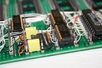
The best way is to use wire wrap is using a perfboard, dip sockets and pin headers, you solder the socket on you perfboard, solder a strip of pin header on each side and connect the socket pins to the pins of the headers. (no need to find special parts excepted the tool) Here is an example :


20120329184235-gc339-Img0276.JPG
 
Last edited by a moderator:
Wouldn't those IC sockets give as bad a connection as a bb?
No, sockets like those have a far better mechanical connection than breadboards.

This kind of sockets are used in arcade PCB without any problem. (even for fast components like RAM)
 
Plus also breadboards have loads of strips all running in parallel. Would have thought at higher frequencies you'd be able to indice significant currents in adjacent lines.
 
Levi - yep, for sure, thast one of the thigns I run into since I'm running at pretty high speed (20MHz). BB's are really suited to 10MHz and lower.

One guy brought up an interesting point, about using a big d-type flipflop as a 'synchronizer'; ie: since I'm using combinatorial logic with MUXes, and various lengths of wire (I tried to keep them the same, mind you), its possible thigs could be sliding around a nanosecond here or there, especially if thigns 'get warm' (not warm enough to feal, but wqarm enough to slow things down just a touch after a few mins), and introducing noise into the TV signal..

My board usually runs fine for a minute or so, then starts to get noisey.

So maybe adding a d-type flipflop (to hold signal and capture it when it starts to rise), may help at least present a non-noisey signal to the VGA. (Or maybe noice due to induction is still a problem.. one dude suggests I need to use thinner wire (less inducing?!!), and run it nicely flat against the BB (and ground plain the BB on a cookie sheet instead of wood.) Thats sort of depressing.. means redoing the Giant BB, getting all new wire and rewiring the whole thing.. a couple nights work .. but maybe it'd help. (I actually tried, if you look at the pics, to keep the blue address line wiring flush to the BB, but theres a lot of wiring and I just lsot room. Maybe the AWG 28-30gauge woudl bne thin enough to fit much nicer. Also, I spaced things nicely, but I could still space further out.. longer wires bad, but more space to run close to BB good?)

Theres just too many unknowns here .. it works okay, but not 'good enough'; if I move to perfboard, it may improve.. or may not; thats what I hate.. don't know :) Going to pcb likely would improve, but I want it to be tight before I commit to _that_ ($$, and long turnaround..)

..

So gotta try a few things :p May need ot buy another 10 BB's and a cookie sheet, tje mew wire spools and some more ICs, and then make another duplicate unit beside this one, so at least I have reference and can compare..... but I dunno.

Maybe now is time to go modular, redesign so I have a CPU board and sync gen board, and a ram board, etc, and then ribbon cables to join them; ribbons seem silly, (long and parallel! you'd think they'd be noisey as hell!) .. but since high speed PCs work fine with ribbons, they must be okay..

But thats a big redesign, and I'd like to see some good results _now_ :)

So .. tempted to plow ahead, get the RAM bus on here working (a pile more wiring...), so I can at least write a basiuc bouncing ball demo or something, and then torch it all to hell..

*hmm*
 
You're probably right, you should get a demo running (bouncing ball or anything that proves that your design works) on your current setup. (since it works for a few minutes before going haywire)

I bet that there will be some people to try to make a Zikzak on perfboards - or even on "real" PCB.

(I may be one of those :rolleyes:  )

When my chinese perfboards will be there, I may buy a not-too-expensive wire-wrap tool ( well, that's still about 80€ for a good one <_<   ) for AWG 30 wire (if my bank account isn't crying from despair at the time :lol:   ). I'll tell you about my feelings about wire-wrap then.

I haven't had time to work on my electronic projects this last week-end, hopefully I'll have some this week.

EDIT : I got most of my capacitors (multilayers and ceramic ones, still missing the electrolytic ones) today. Faster than expected  :)

Now, I'm waiting for my perfboards to get started on my tact switch-based proto-snes-joypad.
 
Last edited by a moderator:
Nice :)

wirewrap 30gauge wire is available at my local shop, $5.95CDN per spool of 50ft, various colours; it does seem intriguing but boy is that wire _tiny_.

The 22gauge is the onyl other stuff they carry thats small (plus much larger sizes); 22 is great for BBing, but when you start massing up the address lines, its just too thick a wad :/

Think I need to source out some 26 or something in the middle.. smaller, without being insanely small; smaller wad, keep it closer to BB, hopefully less noise; maybe redo the giant BB onto a cookie sheet

Amazing there is no 'best practices' FAQ for BB, perfboard, etching, etc, with some 'rules' like these; 'avoid McDonalds arches, stay close to BB' etc :)

I picked up some D-type flipflops .. I'll try inserting one in front of the DAC, see if it helps; may need a pair too, after the MUX before the RAMs, to help settle the signal timings? We'll see..

But going modular may be the way to go :)

I also need to redo the 'gpu' software in asm to get tighter timings, and get the RAM i/o and address bus to the cpu for the bouncing ball or whatever .. then we'll be in action. Add some joysticks (easy) and .. game on :)

We'll see how it goes.. quite some time to invest yet, but we do know the overall design is sound (if crazy!) .. another month or two, we should know if its worth others pursuing it. (If you just buy a dual port RAM, you can toss out 3/4 of the complexity though, but your cost goes up $50 :)

jeff
 
And now, I've got my perfboards and the rest of the capacitors.

That means tomorrow will be a soldering day :D

Yeah, AWG 30 is _tiny_ The great thing is that spools are tiny too :p

I own ten 30 meters spools with different colors, bought for 20€ in china. Quite nice to have so many colors, you can use all the colors to identify the various circuits. 
 
I need to get used to that lead-free tin… I feel like a five years old child would have done a better soldering job than I did!

Worse, I only did the tact switches! I still have to solder two DIP16 sockets, two SIP resistor network and a bunch of wires  :(
 
The only problems I can think of with this design, software-wise is that in forcing people to use double-buffered code, you're forcing them to redraw the whole stage each frame. Certainly on old 8-bit hardware at lower clock speeds that was tricky to achieve. I suppose if the CPU were to remember the sprite positions from two frames ago, it could still paint out those locations before redrawing, but that means actually having to plan and remember things, rather than just using the current values of X and Y for each sprite from last render before invoking new code to calculate new positions.


Hardware wise, how do you cope with switching banks on the fly like that? Does the CPU do any sort of pipelining? If so, it could have done a fetch on one bank and end up writing to the other, if it does fetch and write in separate cycles.


Edit: @Kodeln Sure your soldering iron is hot enough? Lead free's more likely to half melt than old solder. Also, flux.
 
Last edited by a moderator:
@Levi The iron is hot enough, but I need flux. I should have bought a flux pen or something… (the rosin has a maximum t° of 370°. The tin must be used between 315° and 400°. So I set my iron at 360°)
I didn't think about getting flux since I was used to leaded tin, the rosin core was enough to get a nice flow of the tin.
And I guess I should also have made a better cleaning job on the perfboard before soldering.

Anyway, I'll have to make a second prototype of my circuit because I messed up. I put the IC with the d-pad inputs on top of the action buttons and inversely… <_<
looooong wires everywhere on the board YAY

EDIT: Also, next time I'll get tinned perfboards, it should be better for the flowing of the tin.
 
Last edited by a moderator:
Back
Top