Zikzak - crummiest 8bit console/computer ever .. but I'm making it!


yeah I'm working on revisions.. next one is like this, the one after I plan on this and such, etc; ultimately I'm hoping to add some hardware sprite action, and cartridge slot, all the good retro goodness :) Maybe have to find myself a stack of Atari 2600 Combat carts or something, to put into Zikzak with some new eproms inside :p

jeff
 
okay, I think I have the data-lines switching sorted out in my head; lets see if I can remember it until monday when I next get a moment to draw pics :eek:
 
Try to find the hidden stack of ET cartridges buried in the desert xD
 
I'll just leave this here.  Not really on topic, but I can't think of a better audience for it.

For those of you with limited time (it's a short presentation, but it's quite dense and took me a long time to watch) start at around 24m to see the demo in context, but all of it is interesting if you're of the right bent.

Oh, and a warning to Jeff - DO NOT WATCH.  It will make you want to spend more money.  REPEAT, DO NOT WATCH.

Here's a rough index for anyone interested in specific bits and pieces:


0m40s Bio
4m12s Presentation proper starts
7m35s Logic cells
9m30s FPGA structure
11m05s Signalling
13m30s Design software
16m00s Implementing complex logic
20m15s Pipelining
24m15s State machines
25m30s DEMO!
28m10s Demo architecture
29m45s Audio
30m25s Video - VGA
31m30s Audio again
33m00s Video again
34m00s Further reading
34m45s Q&A
 
That's really impressive, but the FPGA are expensive pieces of hardware.

I was interested into an openCores project called OpenARM ASIC, they plan on having an opensource SoC ready at the end of 2013/beginning of 2014.

As of now, they released an FPGA-based dev board to allow hardware engineers to improve the processor and peripherals design (and make a linux distro IIRC).

From what I understand, the design is okay, but still need improvements. The fact is that they want to produce a cheap ARM SoC. The FPGA-board needed to "emulate" that SoC is sold at 150€ (more or less)… So I don't think FPGA is the best way to got for self-thaught electronic tinkerer ;)
 
I've fiddled a bit with FPGA .. I've got a Firebee (Atari ST in FPGA, more or less) board: http://acp.atari.org/

However, I'm building my own retro-styled computer/console, with mostly parts available back in the day 'more or less'; trying not to cheat, as I want to learn digital electronics in a field I'm interested in; FPGAs cheats on the new tech, and means not learning what I want to learn, so I've leaft it aside (though may revisit later.. use one to build a floppy drive emulator for SD or somethign insane, another day :p )

Also, Zikzak will probably cost like $30 in parts or something, nice and cheap :) (not including cases etc :p )

... that all said, I'll check the video out when I get time; the topic list is very appealing :)

..

right now, working on a schematic for the cpu/gpu/IO chips and their communications with memory, so I can start building it onto my board. Once I get this stuff onto the breadboard (big job, hundreds of wires and trying not to pop any parts :eek: ), it'll be quite amazing.. can start writing some basic demos with hardware double buffering.. also have to add serial one of these days, and get a BASIC interpreter going :p .. or maybe add a keyboard?

Anyone know if a very easy to use keyboard?no, best not go there.. shuold stick more with game consoel and serial, not go all the way to computer and keyboard :eek:

jeff

Biggest annoyance is pin-count; if I do 16/17-bit address lines (64/128K), plus 8pin data lines .. a 40pin chip has 8 pins of 'stuff' (power, clocks), leaving you 32bits; right off is .. say 16bit address, 8 bit data, and a few bits control lines.. you're left with maybe 4 general purpose pins. ouch!

.. so then you start going into shift registers for high end address lines (say), convert 8 pins into about 4 (serial pin, a clock pin, .. I forge tif I need ot handle other pins offhand..); convert 8 high end address pins into 2-4 is a bit od savings, but at massive convenience cost.

You can sometimes use data-pins on same lines as address pins, if you're careful, but my memory system is already complicated enough :p
 
Last edited by a moderator:
Yeah, pin-count can be a pain in the back!

That's why DIP package are ok when you do small projects, but when working on larger ones, it's sometime useful to look at surface mounted packages like TSSOP or QFN. With lot of flux and precision, they're not hard to solder.

Bit-shifting components are quite useful, as you can serialize a few of them (like in the SNES joypad ;) 2 static shift register used for a 16bit word), the drawback is that you loose speed.

@comradekingu, if you talk about the zikzak, he is still working on it so the B.O.M. might change :p
 
Last edited by a moderator:
Where can i construct one from basic elements please?

Which? If you mean Zikzak, once its 'done' (are these things ever really done? :) .. but once I have a good solid working base model I'll be making a half dozen or dozen pcboards, and offering a 'kit' if anyone wants to build one.

If you want to build something yourself, on a breadboard or whatever, follow along .. I'll be posting schematics of various partws every little while. I'll be posting a shcematic of the main chunk 'so far' soon, but its all very much in flux.

If you mean something else, can't help you :)

jeff
 
Yeah, pin-count can be a pain in the back!

That's why DIP package are ok when you do small projects, but when working on larger ones, it's sometime useful to look at surface mounted packages like TSSOP or QFN. With lot of flux and precision, they're not hard to solder.

Bit-shifting components are quite useful, as you can serialize a few of them (like in the SNES joypad ;) 2 static shift register used for a 16bit word), the drawback is that you loose speed.

@comradekingu, if you talk about the zikzak, he is still working on it so the B.O.M. might change :p
At the beginning, I avoided SMD parts like the plague, assuming they would be hell to deal with; but once I learnt the 'drag solder' trick (and the solder-paste hot air gun trick), I realize that SMD parts are _easier_ than DIP in a lot of cases.. if you have a pcboard; ie: if you have a SMD->DIP adaptor (like a TSSOP or SOIC to DIP), then life is easy.. I can solder a 64 or 100 pin chip in a couple minutes, like magic. But if you don't have an adaptor, its quite a PITA .. I've done a few RAMs like thism, soldering 28 or 32 wires to the tiny little legs, and I invariably cook off a few legs or something .. some of these 'low format' SOICs are just a meltable plastic case.. heat for more than a second and its all getting loose :/

Theres a bunch of adaptor makers on the net and on ebay, so you can get a number of common adaptors pretty cheaply (5 bucks each with no pins, say), but some of the better ones are like $15-$20 per unit .. for just a ltitle 2" pcboard! Brutal! You can amke your own for a couple of bucks each on a pcboard, so those guys are going for a killing..

I'm honestly tempted to make up a 50 or 100 sheet of little adaptors, and then sell a bunch on ebay; I can only assume however, that the volume is sufficiently low as to render it not worthwhile.. but who knows :p

Anyway, I haven't much fear of SMD parts anymore .. I'm using SOIC32 and TSSOP2 SRAM, and I've already got 'in stock' some TQFP64 and TQFP100 avr models; having 64 or 100 pins completely eliminates a lot of the issues you have, makes things much easier. (Hell, with so many pins, don't even need multiplexers, can just have separate whole sets of pins for each chip :) .. but again, sort of feels like cheating.

I'm thinking of doing full dip (and SMD with dip adaptors) on the breadboard, like now (will show pics later), but when I get to actually etching out or boardhousing pcboards, I may include half SMD components .. keep size (and costs) down, and fun to solder. However, it also increases your window for error .. a slight measurement problem or whatever, and your pcboard design is not going to solder right or something. (I'm not sure how about tight the solder masks can be made at the low run boardhouses, etc. Still to be researched..)

I sort of enjoy the use of shift registers like SIPO or PISO ones, but they do slow things _way down_, which is something I can't really afford; so I may well just cop out and go to TQFP64 avr8 for my cpu and gpu; I've got adaptors in the mail from Thailand for $5ea, that at least get me to SIP form, and then I can put some right-handle headers on there or something to adapt further to DIP, for prototyping. (Can you imagine.. a TQFP100 chip, with an adaptor to two rows of 50 pins .. that obliterates a lot of space on a breadboard.. like an _entire breadboard_ :)

.. Today is Christmas.. just got 5 parcels in the mail from all over the world. I will take a pic of what I received today :) (My wife is very annoyed.. I've been getting 1-3 parcels a week for about 3 months .. most of them are rediculously cheap, but...)

jeff
 
Todays shipments that are relevent to zikzak (not including the drink coaster pcboards someone sent me for lulz):

- PLCC84 to DIP adaptor boards (I've got a couple dual port RAMs that are 84pin SMd PLCC parts, but I may not use them; still, this makes them easy to prorotype with.. socket goes into this board, board goes into breadboard, and you can pop the chips in or out as you see fit.

- SOIC28 / SOP28 adaptor boards (pack of 20 for a couple bucks.. but they're like $2-3/each here locally); most RAMs and such are 32 pin that I've been eyeing, but a few are 28; mind you, at this price, I could possibly hack two of them together :p Still, good to have on hand for quick prototyping, as I've certainly been through a few tiny little chips of these sizes a month ago.. (sometimes the SMD parts are a fraction the price of the DIP ones, since they're modern and thus higher volume; sometimes I can see a RAM go by for a bukc or two in SOIC, that woudl be $20-30 in DIP..)

- DB9 male .. the joystick ports for zikzak :)

These were all free shipping from china, via ebay purchases; pretty sick prices.

parts-shipment-may27.jpg
 
Last edited by a moderator:
The PLCC84 to DIP adapters are impressive :p

Yeah, prices on DIP packages can be high, I still used those on my SNES+ board because people are less afraid to solder them :D

If I used SMC instead if the DIP 4021 et SIP resistor networks, the board could have been a lot smaller! (barely larger than the two connectors)

Status of my searches about tools and components :

I found a few assorted capacitors kits ranging from 400 to 1000 pieces and with prices ranging from 6,95€ to 12,75€ (sometime with 0,70€ of shipping lol).
And I lost my old & rusted side cutters, so I'll order a new one too (probably a cheap and shitty one until I get a job and have the money for good cutters and pliers).

I also want to buy a quality crimping tool, I found a nice one, but 50€ is a bit too much at the moment.
 
Your local electronics supply or hobby store no good for tools eh? I picked up strippers and so on a million years ago for 'okay' prices; online far better nowadays, and ICs and oscilliscopes and so on are pretty mcuh only online.. but you can impulse buy not too badly for some things :)

Caps can add up a bit, depending on the kind; especially if you want those tantalum or mono caps, or the heavy duty ones.. big assorted packs of resistors and diodes are cheaper I think; all told though, shouldn't cost too much for a good pile.

If you find a good capacitor link, let us know; 1000 pieces for 12-pounds ($15ish?) doesn't seem too shabby. I ended up picking up a bag of ceramics, a bag of electrolytic, a bag of monos, and a few tantalums standlone just to have .. gads.

But I stick ceramics all over the damn place.. I shoudl take a pic of my current BB, but I run a line of caps down one side or both sides of all the rails, as it does help smooth out the signal. (ie: 10 caps, just to get a blank BB); I drop a mono cap on each side of an avr (thats 4 or 6 for my current project), and not even gotten going yet :)

jeff
 
Speaking of caps, I never managed to find all the parts to replace the caps in my old Gamegear to fix the audio.  Some weird capacitances in there.

Yeah, I didn't really put the video here as a suggestion to anyone on how to do anything, just as something hardware hackers might enjoy.  Personally, I learned a lot from it, one interesting thing being how long it takes to reprogram an FPGA limiting the benefits of having a field reconfigurable device, but it's nothing to do with making an old-style computer, or indeed a useful way of making any sort of non-clone computer IMO.

Regarding pinouts, I assume that's why there are so many chips in old computers - they have separate chips to handle the video out, I/O, RAM refresh and keyboard - which is how keyboards always used to be done.  Raw row&column lines going into a keyboard controller which decoded them into something, and at least in some cases squirted it into RAM and triggered a NIRQ the get the CPU to deal with it.  Although getting N-key rollover with that sort of setup is quite the contortion act, I'd have thought.  I'd have thought old PC keyboard would be the way to go - the PS/2 keyboard interface is apparently identical to the PC/AT spec, and that has a fairly simplistic interface as you'd expect.  Although it apparently had bidirectional I/O along a single data line which I've seen reference to, but not a complete explanation of - but with an oscilloscope I'd have thought you could decode the spec quite straightforwardly.
 
yeah good call .. I read something about the PS/2 keyboard spec a few months back and it seemed pretty simple at the time; I should, if pin count permits, just slap a port on there and worry about it later ;) (I'm not really using i2c or spi or the like, just bitbanging everythign myself directly, so its not too bad to just deal with these things later.)

I need to sort out cart slots and such too... goodness :) Tonight if I get time I'd like to knock out quick v.01 of the updated schematic of the memory switcher, and then I can refine it a few times and get it into my prototype; busy week, but want to use the time I can get.

Wish I had a week off to bang on this straight, like I did 10 years ago.. I'd have this done in no time :)
 
Jeebus; I think I have about 2/3 of the traces down .. still need to add:


- control lines (and a MUX or two to handle them)


- the data lines (and a couple Latching Buffers to handle them)


Thats just the sram switcher .. a simple concept, but the core of all this business :)

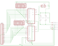
zikzak3-memswitch2.png
 
Last edited by a moderator:
Your local electronics supply or hobby store no good for tools eh? […] oscilliscopes […]
Local hobby stores (no electronic ones around here -_- ) are ok for simple pliers, but for more advanced "weaponry" they're shitty, so I order almost everything from internet (ebay or electronic webstores).


I got a nice (but LARGE <_<  ) second hand 60MHz - 2 channels oscilloscope (HM-605) with a lot of really old and used components and tons of books about amateur radio for 100€ a few years ago. I finally bought a scanalogic-2 as logic analyser (a nice small and cheap piece of kit), since it's quite smaller than the analogic oscilloscope :D .

skeezix said:
[…]


If you find a good capacitor link, let us know; 1000 pieces for 12-pounds ($15ish?) doesn't seem too shabby. I ended up picking up a bag of ceramics, a bag of electrolytic, a bag of monos, and a few tantalums standlone just to have .. gads.


[…]
Here is the 1000pcs set of assorted ceramic capacitors I found, the store has quite a few interesting kits of monolithic ceramic, zener diodes, etc. For the electrolytic capacitors I found another seller with a 13€ - 500pcs kit. Now, I heard that chinese capacitors are sometimes fake… but at that kind of price, even if they are, it's not a tragedy ;)

Now, that's a lot of traces you have there! It tends to get messy when you have lot of components that have to be linked to each other. On my schematics, I had to dissociate the power and ground pins of the two 4021 from their main body, to have less lines crossing each other.

panelboard.png
 
Last edited by a moderator:
Buddy of mine asked the question, and I've been asking myself .. is the CAD view really all that helpful? Honestly.. not; the earlier diagram I showed ("flowchart" "block" that one), is probaby; just as good, if not better (more colours!) and easier to draw (I'm good with that sort of application.) But the CAD version does afford the pinout nicely, and leads right into pcb layout (not sure I'll ever take this to that.. I bet it would be painful and expensive to knock out a few pcboards.. but I would certainly like to :) .. I bet it'll have to be a couple of layers, due to all those traces!

But for connecting it all, I doubt the CAD will help much.. too big, too nasty :)
 
Wife going to kill me, all these deliveries :eek:

Got TQFP adaptors to DIP today; a 32/48/64 to DIP adaptor, and a 64/80/100 adaptor. Theyu're weird triangle ones, but pretty clever in they can hold different size chips on one face.. but annoyingly, have two rows of pins on their bottom edge, so can't breadboard it directly; if it was the rectangular kind, a row of pins on top and bottom edge, be way more handy... still, beggars can't be choosers.

I may go to a 64pin atmega644 instead .. already picked up the mcu's a week or two back.

I've been avoiding 'cheating' the entire time, so I'm on the fence; better to use SIPO shift registers to avoid cheating entirely, but at some point you're creating a lot of extra annoying work, and I know how to do it; so at that point, maybe avoiding cheating is going too far .. so using the same chip, but going to more pins, may be okay :eek: (Mind you, then can't just drop in a z80 or 6809 or 6502, since they are low pincount too .. but would have to redesign anyway, so thats moot.)

Will see :) Gotta see how purist I am here :)

Or as the Dead Kennedy's would put it .. Gimme Convenience or Gimme Death!

jeff
 
OKay, soldering TQFP64 is rather annoying; the pins small enough where even with my velleman magnifier lamp, I can barely see between them .. I've had numerous successes, but I keep forgetting how fragile they are, and the plastic melts if you look at it funny :) I'm doing drag soldering so half the pins work first time swooshing by.. then another quarter with another quick pass.. but those last few that bridge, and you're trying to wick the solder off with quick touches of the iron.. tricky :)

I've got a tqfp64 -> DIP adaptor from Bangkok; had to solder on some header pins and bend them just-so, to give it legs (its standing up 90degrees to the board, like a shark fin).. now putting on the chip.

Guess I'll fiddle with having a 64pin cpu at 16MHz, a 40pin gpu at 20MHz (possibly overclocked to do about 22 or 24..), and we'll see if I need the I/O mcu at all.

jeff

atmega128 has some goofy 'gotchas' up front.

- first one to catch me was.. the ISP programmer needs to hook up to Reset, SCLK, MISO and MOSI (the SPI pins); on most other avr8's, they have MOSI and MISO pins and you just connect away; on this guy however, those are for an actual SPI usart or whatever, but the programmer has to hook up to PD0 and PD1 or whatever.. pins 2 and 3. (Pin1 is "PEN", programmer enable, but the consensus online is no one know2s w-t-f that does ;)

- second one .. the default fuses are set up so the '128 acts like a '103; I assumed this was okay (assumptions always bad in hardware projects!), since they must ship it sensibly, right? Well, turns out if I'm compiling for '128, and its running in '103 mode, everything is horribly messed up. If I bought a '128, I expect it to work like a '128, right? So I had to remove the '103 compatibility fuse. I also turned up internal clock to 8MHz until I can pick up a 16MHz crystal ... and now its working fine! But I assume my programmer not working right was due to '103 compat mode..
 
Last edited by a moderator:
Back
Top