Pandora MSP430 Launchpad and Pandora


MarkoeZ

arr matey?
Joined
May 21, 2008
Messages
1,183
Age
45
Website
projectinfinity.org.uk
Hello People,


This will be a (video) blog about my experiments with the TI MSP430 Launchpad. A week ago i heard about this for the first time. It's a very very cheap microcontroller testboard/breakoutboard, only $4.30. Check This thread on these forums for more info.


The plan is to strip an rc-car, use one or more msp's to control the motor drives, one or more for the sensors, and one to drive the I2C clock of them all and collect and send away instructions.


Now what does this have to do with the Pandora, you might ask. Legitimate question, since the video's i'm posting at first do not even mention the pandora.


Well, the robot will have functions for collision detection and other critical stuff, but since the MSP can do serial connection (as you can see in video 6, controlling the leds of the pad through a virtual com port), and i am expecting WizardStans Pandora ext connectors any day now, the plan is to hook it up to the Pandora, and use that as a central brain. Collecting data and deciding where to go and what to do. And ofcourse a manual override would be available to control it with the pandora's digital buttons, or even the nubs eventually.


At first through the ext connector as mentioned, but later on i want to add a bluetooth module for a wireless conection.


So much for the talk, first testing video's below.


Enjoy!

https://www.youtube.com/embed/odFcJYDk5t0?feature=oembed

http://www.youtube.com/watch?v=XQHsioX6w4A


http://www.youtube.com/watch?v=VZA3SDDxmqA


http://www.youtube.com/watch?v=y-EwhE_hcFI


http://www.youtube.com/watch?v=-gfVuVWUvOU


http://www.youtube.com/watch?v=nYRAa2rz8-U


http://www.youtube.com/watch?v=-txj7uOmaQU


http://www.youtube.com/watch?v=7NydlZmNoTM


http://www.youtube.com/watch?v=egP4_DAfu1o


http://www.youtube.com/watch?v=2MJxunvT5NY


http://www.youtube.com/watch?v=F7yaBuB18sk


p.s. feel free to ask questions and discuss ofcourse :)
 
Last edited by a moderator:
Ok, at this point i'm going to need some help.


I received my Ext connectors, and want to make the pandora talk to the MSP430. The MSP is completely setup to send and receive on 2 serial lines (RX and TX.


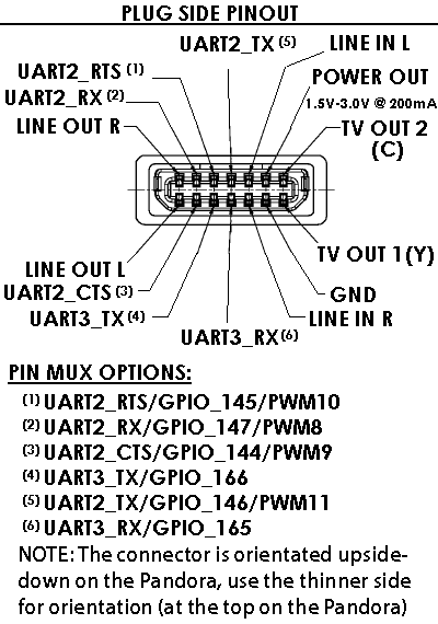
On this diagram i see 2 different uarts:


Cable_connector_pinout.png


Uart 2 and uart 3.


Now how do i connect to one of these from a terminal, or later on in my software? I guess i need the TX and RX lines of uart 3? because a quick google makes me think that uart2 is used for rs232, but i could be totally wrong.


Really, im not looking for anyone to do the developing for me, but im totally new to this stuff, so all help is appreciated.


Cheers!


Edit: some more googling gives me the setserial program. can i do something with that?


Edit2: Ah, also searched through the omap specs, and it seems like im going to need /dev/ttyS1 for uart2 and ttyS2 for uart3. but those show as not active on the pandora. So the question becomes: how do i enable them?
 
Last edited by a moderator:
Interesting. I'm going to try something similar with an AVR microcontroller, once my ext-connectors arrive (and find some time).

Edit2: Ah, also searched through the omap specs, and it seems like im going to need /dev/ttyS1 for uart2 and ttyS2 for uart3. but those show as not active on the pandora. So the question becomes: how do i enable them?
What do you mean by 'not active'? They are there, aren't they? I have ttyS0 to ttyS3 in the /dev directory on my Pandora, and did nothing special.


Also, you probably know the gpio's are 1.8 volts don't you? Have you thought about how you'll get from 3.0 volts to 1.8 volts? Or how you'll power the MSP430?


I'll probably run the AVR on 5.0 volts and rely on the voltage drop from a couple of diodes in series (and hope that'll work). I ordered the voltage regulators MWeston uses in his breakout board, but they are too small to solder. I have bought and soldered some SOIC to DIP converter-boards with the TXB0104 I plan on using.


All these problems go away if we can somehow get 1.8 volts from the ext-connector and run everything on that. The diagram you posted says '1.5-3.0 volts'. Does anyone know more about this? Can this be controlled somewhere?


Edit:

Now how do i connect to one of these from a terminal, or later on in my software? I guess i need the TX and RX lines of uart 3? because a quick google makes me think that uart2 is used for rs232, but i could be totally wrong.
I use this rs232 library to communicate with my AVR's. Works like a charm! You're probably using the rs232 protocol already to communicate with the MSP430 in the terminal. Right? I don't know MS Windows that well, but that's what I think I saw in one of your videos. :)
 
Last edited by a moderator:
What do you mean by 'not active'? They are there, aren't they? I have ttyS0 to ttyS3 in the /dev directory on my Pandora, and did nothing special.
Doh, i made a mistake, they are there indeed. Sorry, pretty much still a linux noob.


So in theory, i could simply hook the wires up and just start communication? (yeah voltage conversion and all, but thats another issue, see below) if so, how? (just through the terminal for now, coding will come later) Edit: hmm, setserial -g /dev/ttyS[0123] shows only ttyS0 with an uart and irq, so guess not

Also, you probably know the gpio's are 1.8 volts don't you? Have you thought about how you'll get from 3.0 volts to 1.8 volts? Or how you'll power the MSP430?
I'll probably run the AVR on 5.0 volts and rely on the voltage drop from a couple of diodes in series (and hope that'll work). I ordered the voltage regulators MWeston uses in his breakout board, but they are too small to solder. I have bought and soldered some SOIC to DIP converter-boards with the TXB0104 I plan on using.


All these problems go away if we can somehow get 1.8 volts from the ext-connector and run everything on that. The diagram you posted says '1.5-3.0 volts'. Does anyone know more about this? Can this be controlled somewhere?

Nope, did not know that. My plan was to first get the pandora to transmit basic random data, and then measure the voltage max on the pins. And planning to use a simple 2 AA battery holder (3v) for the launchpad for first "offline" tests. But afterwards there will be another power source as well, and more converters probably to provide the various circuits.


Edit: Ok, so the pandora's rx can handle 1.8 volts max? Because the launchpad takes 3 volts, so i could just use the power from the launchpads source and a transistor inbetween from pandora to the launchpad. Did not know i could fry anything with 3v back :unsure: But looking for voltage converter then.

I use this rs232 library to communicate with my AVR's. Works like a charm!

Ah, i will look into that, thanks.


And Cheers!


p.s. Lol, you are dutch as well i see :) which part? i live in Tilburg


Groeten!
 
Last edited by a moderator:
So in theory, i could simply hook the wires up and just start communication? (yeah voltage conversion and all, but thats another issue, see below)
I think so, yes. But I'd love to have this confirmed by someone who's really into this sort of thing. Let's say: "I don't see why not, it's how it's supposed to work" :)

Edit: Ok, so the pandora's rx can handle 1.8 volts max? Because the launchpad takes 3 volts, so i could just use the power from the launchpads source and a transistor inbetween from pandora to the launchpad. Did not know i could fry anything with 3v back :unsure: But looking for voltage converter then.
Yes, 1.8 volts only. From the Hacker's manual:

*** NOTE – All digital pins on this connector are 1.8V logic and must be level shifted if they need to be interfaced to a higher/lower voltage system. Failure to do so could result in permanent damage to these pins on the OMAP3530, rendering them inoperable or even creating a short circuit inside the chip.
I don't think you'll get away with a transistor in between (not sure how that's supposed to work). I think we need something like the TXB0104 used in the 'official' breakout board. It's an SMD part, but I bought some converter boards at www.voti.nl (frames, so no direct link) for old school DIP soldering. It needs a 1.8 volt reference, that's why there's also the LP2992 voltage regulator, to go from 3.0 volts to 1.8 volts (that's my understanding of the schematic, anyway. Whatever that's worth). I don't have a converter board for that part. I soldered some diodes in series and I have 1.85 volts now. I hope that'll work.


OR: Skip all of the above, and run everything (including microcontroller) on 1.8 volts for RX and TX, and attach transistors, darlington pairs/arrays, optocouplers, relays and what-not to the rest of the microcontroller pins to control blinkylights, motors, servos, sensors and switches you want to use on any higher voltage.


OR: Skip the ext-connector route completely, buy this cable (~$20,-), plug in the USB port of Pandora, compile the serial library above (or use hyperterminal), connect to /dev/ttyUSB0, and be done with it. (Yes, I want to use the ext-connector too, but this cable is really a great way to get everything up and running fairly quickly. I use this as a prototype.)

p.s. Lol, you are dutch as well i see :) which part? i live in Tilburg
I live on the other side of the country. Groningen. :)
 
Last edited by a moderator:
Hmm, have to give it some thought. Could switch to 1.8v, but that could also mean more conversion to do later on.


But i think i'll order that cable you mentioned anyway. Looks like a nice tool for testing, and will be useful for other projects as well.


Now, some clarification on the ttyS1 and 2 from someone with a bit more pandora-serial-experience would be nice :)
 
Getting more ready for the Pandora Interface, i thought this one could use a small introduction:


Updated from last video, i attached a wire for steering left on the rc car (i fried steering right..) combined the code from the last video with the code from the serial leds, and behold: serial controlled RC car!


Eventually there will be at least 10 states: stop, forward, forward right, right. backward right... *SNIP* ...launch missile, trigger flametorch, whatever.


Also reattached the leds to signal drive forward and reverse. It needs a resistor from the signal port to the transistor, otherwise there is not enough power left available to signal the RC car.


Video Here:


MarkoeZ MSP430 Launchpad Video's Part 11:RC Car controlled through PC Serial Loud Noise Warning!!

https://www.youtube.com/embed/odFcJYDk5t0?feature=oembed

P.s. Also feel free to comment/suggest/critisise or whatever. 430 views and only 2 (very useful!) replies from one guy... ;)
 
Last edited by a moderator:
One more, late evening, video. Soldered connectors to the car and the testboard, showing in the first part. I used audio cables since i have them in all kinds of combinations, so easy extending/splitting/whatever. If i have more channels, i have white and yellow ready as well.


Big plus is, i can screw the board up on the car eventually and directly plug in, or keep it loose and just connect an extension wire while drive testing.


Second part is just for fun, the first drive tests (still using serial)


First test shows: lower the gear. Moving way too fast atm, and could use some more power to get over obstacles. Very funny, but not practical later on


And the video:


MarkoeZ MSP430 Launchpad Video's Part 12: Serial RC car, added connectors and first drive test!

https://www.youtube.com/embed/XQHsioX6w4A?feature=oembed

Cheers!
 
ok, back again. Been testing a very cheap collision detection system, using only an IR Led and a Photodiode.


I started with some reading on this site to get some general info first:


http://www.societyofrobots.com/sensors.shtml (good site anyway,lots of explanations and tutorials on robotics, sensors, motor drive, etc.) .


Then i used the code from this site:


http://gushh.net/blog/msp430-launchpad-led-as-photodiode/


and started hacking away at that.


As the video shows, working pretty nice.

https://www.youtube.com/embed/VZA3SDDxmqA?feature=oembed

Also general update: The eventual project i have in mind will not use the rc car as base. I want 2 drive motors for the main back wheels, individually controllable for fast turning. But also wheel rotation sensors to make sure they travel the same distance and front wheel steering for fast travel forward. But already almost running out of pins, so going to need more (and/or different) MSP's, shift registers, boards, connectors and what more probably. Should be fun :)


Cheers!


p.s. usb cable is coming, so should have a pandora interface within 8 working days....


p.p.s. i still think this is not exactly the right section, but it's not off topic either; The pandora interface will happen sooner or (slightly) later
 
Last edited by a moderator:
Next step: I started work on the first implementation of a drive mechanic, combining the sensor and drive programs. Will be more refined, with better sensors, but just working toward something driving now. Serial is not doing anything, but framework present in the code.


Also have some ideas about how to build all the extra boards and components into the original porsche shell (will do a rebuild on smaller board, and also buy a dremel). So there will only be an usb cable going in there eventually, when the usb serial cable arrives.

https://www.youtube.com/embed/y-EwhE_hcFI?feature=oembed

Cheers!
 
I'm enjoying your videos and progress :)


Just to let you know, my experiments with the voltage-shifting are coming along nicely. I soldered up a board that has specific points with different voltages. There's the input-voltage (9V in this case), 3V3, 3V0 and 1V8. On the top of the board I plan on using a 5V0 regulator to drive an LCD display (well, that's the plan *now*. Knowing myself a little bit, this'll probably change).


On the bottom of the board there's the TXB0104 (4 ports voltage level shifter) on a green converter board. It's a very easy to solder SMD component. Send up to 5V5 to pin B1, and get 1V8 (reference voltage) on pin A1. It's bi-directional, it figures out itself what to do. Pretty neat! I'm 99.9% positive my ext-port on the Pandora won't blow up.


voltboard.jpg


I've also been experimenting with the FT232 chip, the one in the FTDI-cable. It's a little harder to solder (more and smaller pins), but it's working like expected. The lesson I learned here is to not solder some schematic by the first random Joe on the internet, but actually solder the schematic found in the FTDI datasheet. Doh! It's also able to interface on 1V8. That might come in handy communicating between the Pandora and a PC/Laptop with a USB cable. You might not be interested in that, but I thought I'd mention it anyway.


Other offtopic stuff:


I have the 3V3 version of the FTDI cable. It's 5V tolerant. I use it on 5V most of the time.


Also, I suspect there are kernel messages being sent to the serial port at the moment. Those will probably interfere with the commands you send to your car. I'm sure there's some way to turn that of. Don't know how. Another thing to find out.


Edit: Using the FTDI cable this will not be a problem, of course.
 
Last edited by a moderator:
I'm enjoying your videos and progress :)


<snip>

Thanks! Feedback is always welcome, and positive even more :)


Looking forward to more of your progress as well, keep us updated! And feel free to use this thread until you have big breakthroughs and want to create your own (the first of "the public" with working pandora serial ext port perhaps?).


And for now i'll just be using the usb cable (when it arrives). There are still so much things that are new to me and i need to research, the extra hassle of the pandora ext port is just too much atm (also hoping someone else figures it out soon, hint hint ; )


But i will need voltage conversion circuits as well. Launchpad is running at 3 volts, sensors at 5 volt, and the motors i plan on using eventually are 12 volt, 5 line, stepper motors with rotation sensor. Hoping to use shift registers for those so i don't have to use 5 pins of an msp. But not sure if that's even possible, another thing to research. Edit: That in fact appears to be the proper way to drive a stepper motor.


I also obtained a partly defective circuit board, containing 2 nice rs232 line driver/receiver chips (that i think i can use for some of the voltage conversion, i read something like that somewhere, not sure), an eepot, a quadruple bus tranciever (not even sure what that does yet, but a quick glance at the datasheet makes me think it will be usable in the future), and loads of other useful small stuff like zener diodes and such.


Cheers!


Edits: just layout and clarifications, it's late.
 
Last edited by a moderator:
I'm enjoying your videos and progress :)


<snip>

Thanks! Feedback is always welcome, and positive even more :)


Looking forward to more of your progress as well, keep us updated! And feel free to use this thread until you have big breakthroughs and want to create your own (the first of "the public" with working pandora serial ext port perhaps?).
Thanks! I'll create that thread one day, just thought I'd keep you updated in the mean time. Still waiting for ext-connectors.

And for now I'll just be using the usb cable (when it arrives). There are still so much things that are new to me and i need to research, the extra hassle of the pandora ext port is just too much atm (also hoping someone else figures it out soon, hint hint ; )
That's totally understandable. The FTDI cable is so much easier to work with, and it makes the project also usable on any laptop/PC (including the Pandora) in stead of 'just' the Pandora. The main reason I want to use the ext-port is 'just because'. Which is a perfectly valid reason as well, I think. :)

But i will need voltage conversion circuits as well. Launchpad is running at 3 volts, sensors at 5 volt, and the motors i plan on using eventually are 12 volt, 5 line, stepper motors with rotation sensor. Hoping to use shift registers for those so i don't have to use 5 pins of an msp. But not sure if that's even possible, another thing to research. Edit: That in fact appears to be the proper way to drive a stepper motor.
A nice thing about a shift register like a 74HC595 (serial in, parallel out) is that you can connect them in series, for an unlimited amount of outputs. If you have 1, send 1 byte to control 8 outputs. If you have 8, send 8 bytes to control 64 outputs. You can't draw too much current from them however (just a few mA). You might want to look at something like a ULN2803 in combination with the shift registers. You can draw 500 mA from each pin, and even combine pins if you need to draw more current from them.


In case you need more inputs, something like a 74HC165 works the same way as a 74HC595, but the other way around (parallel in, serial out). In theory it should be possible to combine the clockpin and the latchpin for both series of shift registers. That means an unlimited amount of digital inputs and outputs with just 4 pins (maybe 5) on your microcontroller.

I also obtained a partly defective circuit board, containing 2 nice rs232 line driver/receiver chips (that i think i can use for some of the voltage conversion, i read something like that somewhere, not sure), an eepot, a quadruple bus tranciever (not even sure what that does yet, but a quick glance at the datasheet makes me think it will be usable in the future), and loads of other useful small stuff like zener diodes and such.
Have fun with that :)
 
Last edited by a moderator:
Thanks for the tips again!


And i placed a large order today: ultrasonic range finder, servo, an FT232 breakout board, 3 74HC595 shift registers, pre made logic level controllers (at only 1,50 i had to get 2), some adjustable voltage regulators (that can handle up to and beyond 12 volts easily) and a whole bunch of general components.


Also requested some MSP430 samples from TI, hope that gets approved. Then i have more processing power to drive everything.


Should be nev video's this week :)
 
That's the spirit! Why buy one, if you can buy two, twice the price?


Three, thrice?


Yay for new toys! :lol:
 
That's the spirit! Why buy one, if you can buy two, twice the price?


Three, thrice?


Yay for new toys! :lol:

Lmao, well yeah, with shipping at some companies being up to 10 euro, i decided to stock up a bit for future projects. And voltage converters and shift registers for instance are pretty cheap and commonly used parts. So will be useful probably.


Edit: and i see a shipping mail from TI in my inbox, 3 MSP's coming my way :D
 
Last edited by a moderator:
Smart decision to buy the breakout board!


I just had to be the cheapskate and bought the single chip (~$ 3,50). End result: a working board, but with a mess of wires and components and one hell of a headache!


Since I plan on working towards using some PCB-service for the board I think have to bite the bullet, though.


It looks like you're having loads of fun. Keep it up! :)
 
Last edited by a moderator:
Back
Top