hmc
Active Member
Update 2014-01-15:
The configbutton plugin for this mod is now available for download from my homepage:
http://www.hermocom.com/pandora-customizing-hw
----------
Hi guys,
this hardware hack may be interesting for people, who want to use the Pandora in "laptop" mode in the dark.
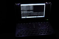
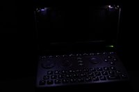
It adds two LEDs, that illuminate the keyboard strongly enough, that even the blue "Fn"-ed symbols on the key caps are visible, if the surrounding is totally dark.
But unlike cube84's keyboard light hack, the LEDs are not mounted into the hinge tube, but at the top border of the screen. This method was inspired by one of the IBM Thinkpads. I think it was the T61, which had a single LED on top of the screen, that illuminated the keyboard very well.
Also, it was kind of inspired by the LED light I have built many years ago for illuminating the HP Palmtops' LCD screen.
cube84's method works well, if the screen is opened with the default resting opening angle of almost 180°.
My method is more suitable for situations, when you have an opening angle of about 90° to 140°, i.e. if you use the pandora similarly to a laptop.
(See also my article about the hinge resting angle hack)
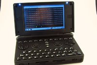
The following pictures have been taken in total darkness, with only the Pandora's screen and keyboard LEDs switched on (one with the screen switched off to show the effect of only the LEDs):

So, here are the step-by-step instructions:
Stop. Before you begin: Consider, that you void your warranty when hacking the hardware!
What you need in addition to your Pandora is this:
Choosing the parts to use:
Step 1:
Disassemble the Pandora entirely, following the instructions from EvilDragon's video.
Step 2:
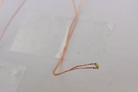
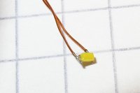
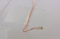
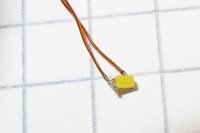
Solder thin insulated wires of about 10 cm each to the two SMD LEDs.
Step 3:
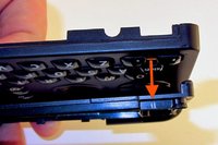
Mark the positions where the screen bezel needs slits for the LED wires.
These positions should be between keys, so that the LEDs won't collide with keys, when the lid is closed.
Do this on both sides.
Step 4:
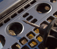
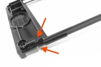
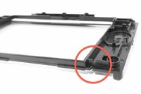
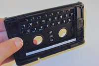
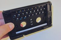
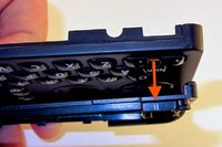
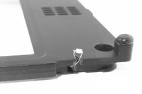
Use a fine rasp or another suitable tool, to saw the needed slits into the screen bezel. See photos:
Step 5:
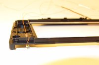
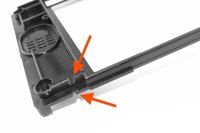
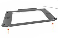
Place the two LEDs and lead their wires through the slits. Use scotch tape to fix the wires to the screen bezel, as shown on the photos.
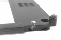
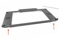
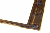
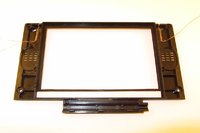
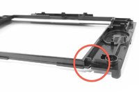
Make sure that the LEDs don't stick out more than the plastic corners of the bezel. Otherwise they will collide with the keyboard later:
Step 5:
Test the LEDs. For that purpose, connect them both in parallel to a 3.7V voltage source, using the correctly calculated resistance, according to these schematics:

Step 6:
Assemble the screen module according to EvilDragon's detailed instructions (video).
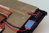
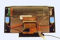
Connect the LED wires, the resistor and two additional wires, that will be used for the LEDs power supply. For making this more convenient, you may use a small piece of circuit board. Take care, that everything is well insulated. You may use scotch tape to make sure, that the wires and the small piece of circuit board stay in place.
Step 7:
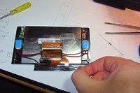
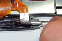
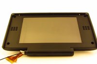
Roll the screen cable according to EvilDragon's detailed video instructions. When leading the antenna cable through the screen cable roll, also lead the two LED power supply wires through that roll.
Step 8:
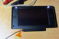
Now it's a good time to test, if the LEDs still work.
Connect the 3.7V voltage source to the LED power supply wires again and check the LEDs.
Step 9:
In all the following assembly steps shown in EvilDragon's video, take care about the new additional LED wires.
Stop the reassemlby, if you reached the part in the video where the screen cable connector has been connected to the motherboard.
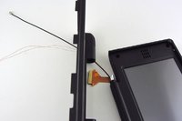
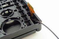
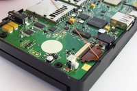
Step 10:
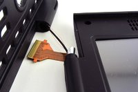
Now you need to connect the LED wires to the KP_BL pads on the motherboard.
You can of course directly solder the wires to the pads.
I chose to use a little plug, so I can easily unplug the cables when I disassemble the Pandora again. The photos show the details, how I prepared the plug etc.
Whatever you do, take care that nothing (neither the wires, nor the plug) collide with parts of the case or with prominent components on the motherboard. Don't cut the cables too short. You may need to lead them in a non-direct way (see next step).
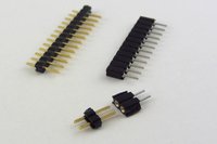
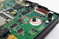
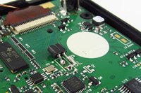
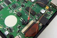
Step 11:
Lead the wires in a route, that they won't be squeezed by the mechanical mainboard supplies of the bottom case after reassembly:
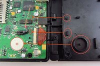
Step 12:
Reassemble the Pandora completely (see video).
Step 13:
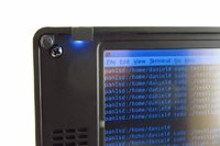
You may glue small pieces of black plastic in front of the LEDs, in order to avoid that the LEDs will blind you. I used little rectangles cut out of a piece of black heat shrink tubing.
Step 14:
Now comes the software part.
The KP_BL line of the Pandora is supported by the kernel of the Pandora OS.
If you write a value from 1 to 255 into
"/sys/class/leds/pandora::keypad_bl/brightness"
the LEDs will be switched on. The line uses PWM (pulse width modulation), so it is possible to adjust the brightness of the LEDs, using values of 1 .. 255. Value 0 switches the LEDs off again.
In my case, it seems to be good to use the values:
0 (LEDs off)
64 (LEDs on, middle brightness)
255 (LEDs max brightness)
So, switch on the LEDs using these commands:
sudo su
<enter password>
echo 255 > "/sys/class/leds/pandora::keypad_bl/brightness"
Also, you may enjoy this little script ;-)
Have fun!
Daniel
This post has been promoted to an article

The configbutton plugin for this mod is now available for download from my homepage:
http://www.hermocom.com/pandora-customizing-hw
----------
Hi guys,
this hardware hack may be interesting for people, who want to use the Pandora in "laptop" mode in the dark.
It adds two LEDs, that illuminate the keyboard strongly enough, that even the blue "Fn"-ed symbols on the key caps are visible, if the surrounding is totally dark.
But unlike cube84's keyboard light hack, the LEDs are not mounted into the hinge tube, but at the top border of the screen. This method was inspired by one of the IBM Thinkpads. I think it was the T61, which had a single LED on top of the screen, that illuminated the keyboard very well.
Also, it was kind of inspired by the LED light I have built many years ago for illuminating the HP Palmtops' LCD screen.
cube84's method works well, if the screen is opened with the default resting opening angle of almost 180°.
My method is more suitable for situations, when you have an opening angle of about 90° to 140°, i.e. if you use the pandora similarly to a laptop.
(See also my article about the hinge resting angle hack)
The following pictures have been taken in total darkness, with only the Pandora's screen and keyboard LEDs switched on (one with the screen switched off to show the effect of only the LEDs):


So, here are the step-by-step instructions:
Stop. Before you begin: Consider, that you void your warranty when hacking the hardware!
What you need in addition to your Pandora is this:
- 2 LEDs. I used Osram LW L283. These are *very* small. You might use slightly larger ones for convenience.
- thin insulated wire
- a suitable resistor. You need to calculate the one you need, individually for your used LEDs.
- a fine soldering iron
- scotch tape
- various tools like screw drivers, a small file (fine rasp) or saw, small pliers etc.
- a 2-contact jack/plug pair, that's small enough to fit into the Pandora (alternatively you may solder the LED's wires directly to the KP_BL pads on the motherboard)
- a small piece of circuit board for easier connecting the wires and resistor
Choosing the parts to use:
- LEDs:
You can use almost any kind of SMD LED, that's small enough to fit the available space, and that has standard LED characteristics (forward voltage around 3V, forward current up to about 50mA).
Note that the KP_BL line of the Pandora can at most supply 160mA, so two LEDs with 80mA would be the limit.
Data sheet of the LEDs I used.
- Resistor:
Now calculate the value of the resistor you need. For that, you need the typical forward voltage and the forward current of the used LEDs. You put the LEDs in parallel, so you need twice the forward current.
The KP_BL pads on the Pandora's mainboard supply 3.7V (supply voltage, V_s).
The resistor is calculated using this formula:
R = (V_s - V_f) / I
Forward voltage (V_f): 3.1V (typ)
Forward current per LED: 20mA
I.e. I = 40mA = 0.04 A for both LEDs.
Calculation of the needed resistor (R = U / I), you can use this online app as a help.
With V_f_typ = 3.1V:
R = (3.7V - 3.1V) / 0.04 A = 15 Ohm
With V_f_max = 3.5V:
R = (3.7V - 3.5V) / 0.04 A = 5 Ohm
I measured the really flowing current with different resistors:
20 Ohm: 30mA (i.e. 15mA per LED), weak light
10 Ohm: 40mA (i.e. 20mA per LED), good light
1 Ohm: 50mA (i.e. 25mA per LED), very bright light
So I chose to use a 10 Ohm resistance.
- The Pandora hacker's guide, section "9) SPARE KEYPAD BACKLIGHT":
(this is the place where the LEDs will be connected to)
- EvilDragon's video showing disassembly and re-assembly of the Pandora. Actually it is about replacing the display cable, but it includes the entire process of dis- and re-assembly, so you need to do everything shown in that video, except replacing the screen cable. ;-)
http://www.youtube.com/watch?v=l8GfjAsbmK8
Step 1:
Disassemble the Pandora entirely, following the instructions from EvilDragon's video.
Step 2:
Solder thin insulated wires of about 10 cm each to the two SMD LEDs.


Step 3:
Mark the positions where the screen bezel needs slits for the LED wires.
These positions should be between keys, so that the LEDs won't collide with keys, when the lid is closed.
Do this on both sides.

Step 4:
Use a fine rasp or another suitable tool, to saw the needed slits into the screen bezel. See photos:


Step 5:
Place the two LEDs and lead their wires through the slits. Use scotch tape to fix the wires to the screen bezel, as shown on the photos.


Make sure that the LEDs don't stick out more than the plastic corners of the bezel. Otherwise they will collide with the keyboard later:

Step 5:
Test the LEDs. For that purpose, connect them both in parallel to a 3.7V voltage source, using the correctly calculated resistance, according to these schematics:

Step 6:
Assemble the screen module according to EvilDragon's detailed instructions (video).
Connect the LED wires, the resistor and two additional wires, that will be used for the LEDs power supply. For making this more convenient, you may use a small piece of circuit board. Take care, that everything is well insulated. You may use scotch tape to make sure, that the wires and the small piece of circuit board stay in place.


Step 7:
Roll the screen cable according to EvilDragon's detailed video instructions. When leading the antenna cable through the screen cable roll, also lead the two LED power supply wires through that roll.


Step 8:
Now it's a good time to test, if the LEDs still work.
Connect the 3.7V voltage source to the LED power supply wires again and check the LEDs.

Step 9:
In all the following assembly steps shown in EvilDragon's video, take care about the new additional LED wires.
Stop the reassemlby, if you reached the part in the video where the screen cable connector has been connected to the motherboard.


Step 10:
Now you need to connect the LED wires to the KP_BL pads on the motherboard.
You can of course directly solder the wires to the pads.
I chose to use a little plug, so I can easily unplug the cables when I disassemble the Pandora again. The photos show the details, how I prepared the plug etc.
Whatever you do, take care that nothing (neither the wires, nor the plug) collide with parts of the case or with prominent components on the motherboard. Don't cut the cables too short. You may need to lead them in a non-direct way (see next step).


Step 11:
Lead the wires in a route, that they won't be squeezed by the mechanical mainboard supplies of the bottom case after reassembly:

Step 12:
Reassemble the Pandora completely (see video).
Step 13:
You may glue small pieces of black plastic in front of the LEDs, in order to avoid that the LEDs will blind you. I used little rectangles cut out of a piece of black heat shrink tubing.

Step 14:
Now comes the software part.
The KP_BL line of the Pandora is supported by the kernel of the Pandora OS.
If you write a value from 1 to 255 into
"/sys/class/leds/pandora::keypad_bl/brightness"
the LEDs will be switched on. The line uses PWM (pulse width modulation), so it is possible to adjust the brightness of the LEDs, using values of 1 .. 255. Value 0 switches the LEDs off again.
In my case, it seems to be good to use the values:
0 (LEDs off)
64 (LEDs on, middle brightness)
255 (LEDs max brightness)
So, switch on the LEDs using these commands:
sudo su
<enter password>
echo 255 > "/sys/class/leds/pandora::keypad_bl/brightness"
Also, you may enjoy this little script ;-)
#!/bin/bash
for j in {1..10}
do
for i in {0..180}
do
echo $i > /sys/class/leds/pandora\:\:keypad_bl/brightness
sleep 0.005
done
for i in {180..0}
do
echo $i > /sys/class/leds/pandora\:\:keypad_bl/brightness
sleep 0.005
done
done
for j in {1..10}
do
for i in {0..180}
do
echo $i > /sys/class/leds/pandora\:\:keypad_bl/brightness
sleep 0.005
done
for i in {180..0}
do
echo $i > /sys/class/leds/pandora\:\:keypad_bl/brightness
sleep 0.005
done
done
Daniel
This post has been promoted to an article


Last edited by a moderator:


