Unbricking gp2x


Todespreis

Member
Joined
Jun 16, 2021
Messages
83
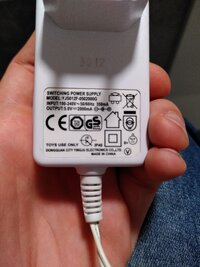
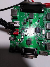
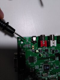
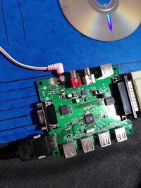
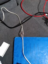
Hey there! I need some help unbricking my gp2x. I got a breakout board, all the cables and software. But i don't have the right power supply. I searched on ebay and found some with 2 amps and 5 Volts. Now i got a similar one (Picture), but the breakout board does not turn on. It only gets hot on the point 2R2 (Picture). So i checked the the Voltage of my power supply with my multimeter, it' constantly on 5.2 Volts (i think, my power supply is'nt correct, it's a cheap one) and the amps are pending between 0.3 and 1.2. Maybe i'm just too stupid to messure it? Maybe the power supply is broken? Maybe the breakout board is broken? I mean, the power supply has some voltage on it, but the breakout board does not turn the green light "ON" (Picture). Does anyone have a working breakout board an could say, what do i need to get it working?
 

Attachments

  • IMG_20210911_203957.jpg
    IMG_20210911_203957.jpg
    5.8 MB · Views: 163
  • IMG_20210911_204051.jpg
    IMG_20210911_204051.jpg
    5.4 MB · Views: 159
  • IMG_20210911_204125.jpg
    IMG_20210911_204125.jpg
    4 MB · Views: 159
If it's a barrel plug, make sure the poles are correct. Some are wired "the wrong way". Why there's heat - no idea. Don't think a blocking diode would get hot, would it?
 
5.2V out of a 5V power supply sounds pretty good to me; you don't want it under 5 and only 0.2V over is pretty good. Obviously, the power supply controls the voltage and the break out board controls the current, so if it's fluctuating that sounds like it's doing something.

I wonder how you're measuring the current however. It's generally a much more involved process, because your meter should have separate ports for measuring current which have a very low resistance to the common port. You need to insert it in the circuit to measure current which either means cutting traces, or stringing the power supply plug with leads so you can insert the meter in one of the ways in (I usually splice it in the positive lead, but I don't think it actually matters which you use).

But assuming you are reading current correctly, seems reasonable values. I'm not sure what the componet labelled 2R2 is, by name it sounds like a resistor, but in the picture form I don't think it necessarily is. Could be an inductor, could be a weirdly coloured capacitor; it's next to some old style mini electrolytic surface mount caps. But it getting hot on dissipating a voltage is what resistors do, so maybe it's a weird shaped resistor after all.
Post automatically merged:

If it's a barrel plug, make sure the poles are correct. Some are wired "the wrong way". Why there's heat - no idea. Don't think a blocking diode would get hot, would it?
Diodes in my experience generally fail short, but I think it may depend on what sort they are. But yeah if it's failing short or failing completely open it shouldn't dissipate a lot of heat either way. Diodes do get hot in normal operation though, they need to output heat to make up for that voltage drop.
 
inductor.jpg
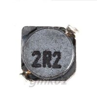
That component is an R2R = 2.2uH (H = Henry) inductor. On the board it's labeled as L3, a naming convention to refer an inductor. An inductor doesn't have a polarity.
It's normal for an inductor to be somewhat warm, with over current it can become really hot.

Can anyone confirm the breakout board needs 5V, as the unit itself is 3.3V?

According to this link the unit is 3.3V and the cradle is 5V, but is this breakout board the same as the cradle?
This wiki also indicates that the unit has center ground while cradle is center positive.
Center positive icon on adapter:
center_positive.jpg
 
Hi! Thank you all for the replies. I got the breakout board working. Just needed to switch wires, because the power supply had a centre positive and the board needs it negative. But i can't unbrick the gp2x. I'm not sure how the firmware should look on an sd card, maybe i miss some files or the files are in the wrong directory. Anyways, Jtag software says "sucsess", so it has to be the firmware. I will try it out later
 

Attachments

  • IMG_20210911_233333.jpg
    IMG_20210911_233333.jpg
    6.4 MB · Views: 159
  • IMG_20210911_233338.jpg
    IMG_20210911_233338.jpg
    7.5 MB · Views: 165
Back
Top