Power pin to GPIO safe?


Nardella

Member
Joined
Mar 4, 2011
Messages
352
I want to add buttons to my Pandora via the EXT port.


Is it safe or recommended to connect the power pin to a GPIO pin?


Should I connect to GND instead?


Or do I need a more complex solution perhaps involving resistor(s) and/or more than two pins?
 
Last edited by a moderator:
You do not want to connect the powerpin to any of the GPIO's. The problem is there's 2.8V on the power-pin, and the GPIO's can only handle 1.8V. It will probably work for a few seconds. After that, the GPIO-pin is damaged.


There are some ways to get to 1.8V:


- voltage regulator


- voltage divider


- Wait for notaz to regulate the voltage on the powerpin in the firmware


- Use 1 GPIO-pin as an output (so it has 1.8V), and use that to 'drive' the inputs (not 100% sure how/if that'll work).


You'll want to read into pull-up and pull-down resistors. Some microcontrollers have built-in pull-up resistors (activated in software), so you can connect those input-pins directly to ground without damaging anything. I don't think the GPIO's on the Pandora have those, and I'm a bit reluctant to test it out to be honest.


Once you have the 1.8V, you'll want a pull-up resistor when you connect the pin to ground, and a pull-down resistor when you connect the pin to 1.8V.


I wish this was easier. Really, I feel your pain. :)
 
Last edited by a moderator:
Most of the pads on OMAP3530 have the option for internal pullup or pulldown. You want to configure the GPIO for internal pullup and connect the switch to ground. When the switch is open it'll be pulled up and read 1, and when it's closed it'll short to ground and read 0.


You might expect for the pullup/pulldown configuration to happen in the GPIO setup, but since it's tied to physical pads it's done in the system control module. You want to look for the register CONTROL_PADCONF_X that corresponds with the GPIO block you want. For instance, let's say you're using GPIO 147 on pin 1 of the ext connector. To set this up you need to use CONTROL_PADCONF_UART2_TX. You can see on page 775 of the reference manual that GPIO 147 is set as mux mode 4 on this pin. So you'll want to set the low 3 bits to 4 to set this mux mode, set PULLUDENABLE to 1, PULLTYPESELECT0 to 1, INPUTENABLE0 to 1, OFFENABLE0 to 0, and WAKEUPENABLE0 to 0. I think that should be it.


Then you have to set the GPIO control. Set bit 19 in GPIO_OE bank 5 to 1.


The one caution is that if this pad is somehow set as output and driven (instead of pulled) you'll have a problem because there'll be a short, which could result in damage if there isn't enough impedance elsewhere to catch it. The pin I picked is normally set for UART RX so you'd think this wouldn't happen (in other words, don't pick something that has a normal use case as an output). If in doubt you can prevent damage by pulling the switch down to ground instead of connecting directly to it. You would have to use a pull down resistance value that is substantially less than the internal pull up value, in order for it to be sure to override it. The internal pull up drives 100 uamps at 1.8V, so it's 18KOhm resistance. An order of magnitude less (say, around 2K) should be sufficient.


Failing that, make sure that the register configuration is right before connecting anything to it.
 
Last edited by a moderator:
Looks like all this is well beyond my understanding :( I was really hoping it would be much simpler, I had asked a few people in chat and was told it should be as simple as connecting one of the GPIO pins to a gnd or power pin with a button and then running some kind of script on the device.


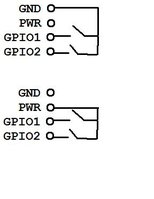
I don't think I will be able to do anything on the software side safely as it seems that if I do something wrong with the software I could damage my Pandora. As for hardware, it should be pretty simple for me once someone tells me what I have to connect where with what parts.


For the person asking for a circuit diagram:


Circuit for buttons.jpg
 
Last edited by a moderator:
Don't feel bad, it's actually healthy to feel daunted when you're told to look in a 3456-page reference manual to get some buttons going. Look! It's right there, on page 775. Easy, just set these bits in these registers and off you go!


If I understand Exophase correctly, he was explaining how to enable the built-in pull-up and pull-down resistors on the GPIO pins (they are there after all!). That's actually very valuable information, so thanks for that! But it scared the hell out of me too. :)


That doesn't mean that *has* to be done for your idea to work. It could also be achieved by external pull-ups (see that pullup/down link I posted).
 
Last edited by a moderator:
I have noticed that both Snes9x4) and PCSX ReARMed both recognize "gpio-keys" as an input device. Does anyone know anything about this?
 
Back
Top