Here is the idea:
I want to use my pandora to send sms. (from cli)
So I got this:
 www.xitekltd.com
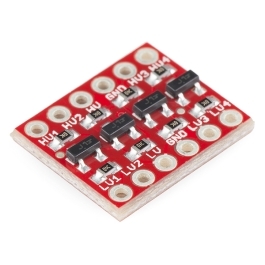
And I learned, I shoud use a levelshifter on the RX/TX signals, guess this will do:

 www.sparkfun.com
Modul itself shoud be povered directly from the LiPoly,as the ext connectors voltage is to low.
-Feel free to point me to a GSM modul which will operate with the ext-connector directly. I didn't found one.
The final setup should be this:
By using a shorter Battery of the same capacity, placing the modem inside the battery compartment and connect it to the internal ext port pins on the mainboard. An external antenna should fit inside the case beside the stylus or in the battery compartment, too.
For testing, I intend to use the ext connector at the back of the pandora, of course.
Information I am lacking so far:
- are those ext serial pins sufficient to communicate with the modul?
(or more accurate: are those addressable as /dev/ttyX ?)
- are there any CAD files of the Battery lid (in case I need a modified one later on)
- ok it seems the levelshifter needs stable input voltage for the hight and the low side. so a regulated source for 1.8 and 3.3 V is needed to make tis working? are those available somewhere on the board?
It is in no way a thoroughly thought through concept, but if anyone is out to help me get this running, I at least would spend a second bundle of components in as a reward (including a modified 3D prind of the lid)
I want to use my pandora to send sms. (from cli)
So I got this:
Product view
 www.xitekltd.com

SparkFun Logic Level Converter - Bi-Directional
The SparkFun bi-directional logic level converter is a small device that safely steps down 5V signals to 3.3V AND steps up 3.3V to 5V at the same time.
-Feel free to point me to a GSM modul which will operate with the ext-connector directly. I didn't found one.
The final setup should be this:
By using a shorter Battery of the same capacity, placing the modem inside the battery compartment and connect it to the internal ext port pins on the mainboard. An external antenna should fit inside the case beside the stylus or in the battery compartment, too.
For testing, I intend to use the ext connector at the back of the pandora, of course.
Information I am lacking so far:
- are those ext serial pins sufficient to communicate with the modul?
(or more accurate: are those addressable as /dev/ttyX ?)
- are there any CAD files of the Battery lid (in case I need a modified one later on)
- ok it seems the levelshifter needs stable input voltage for the hight and the low side. so a regulated source for 1.8 and 3.3 V is needed to make tis working? are those available somewhere on the board?
It is in no way a thoroughly thought through concept, but if anyone is out to help me get this running, I at least would spend a second bundle of components in as a reward (including a modified 3D prind of the lid)
Last edited:

