Zikzak - crummiest 8bit console/computer ever .. but I'm making it!


I'm still laying all the basics down (both in software and hardware). Making sure I can compile and upload everything on the Pi, communicate on all the channels I want and nothing is in the way of each other. To test the data streaming with node, I'm just reading out a potmeter on an analog pin. Nothing fancy :) That works, on to the next thing.

What you said, fun versus time.
 
Schematibs and pcb layout for power and gpu proto pcbs are done! Will post pics in a couple hours..

Candidates anyway.

Annoyingly, elecrow is down right now so can't place the order .. Was hoping to get in today so they can ship in midweek.. Last time I had a one week door to door :)

Routing than gpu was interesting .. Autorouter didnt work at all and make a mess anyway so fun to do it by hand; ERC doesnt say any crossed wires but I'll give it a good trace inspection tonight..

edit: They got their site back up after some half-day out outage (love it.. they announced Wednesday a new website and server update.. Friday, down all day :)

--> I've rushed through the CAM processing scripts and fed the file up to them; $30, what the hell .. bring it!

--> yes, I ran the design rule check first .. had to adjust some spacings, and it caught 2 little overlaps when I had traces going through vias and going a little too close to top-side through-hole on the underside-traces. Nice!
 
Last edited by a moderator:
OKay, picture time .. rev1 for power and GPU prototype pcbs.

There were a few small changes after these images were made. (ie: yes, some of the text on the gpu was on bPlace instead of tPlace; I caught that when reviewing the gerbers and fixed 'em)

GPU r1

schem: https://raw.githubusercontent.com/skeezix/zikzak/master/zik80/schem/zik80-gpu-schem-002.png

pcb: https://raw.githubusercontent.com/skeezix/zikzak/master/zik80/schem/zik80-gpu-pcb-002.png

Power r1:

schem: https://raw.githubusercontent.com/skeezix/zikzak/master/zik80/schem/zik80-pwr-schem-002.png

pcb: https://raw.githubusercontent.com/skeezix/zikzak/master/zik80/schem/zik80-pwr-pcb-002.png

Power pcb is pretty straight forward, hopefully that sucker works fine..

GPU is a pretty hairy routing job; hopefully I didn't cross any traces .. design rule check should've caught anything, but I'll worry until it arrives and tests ok :) Still, my 2nd only pcb design where I manually routed traces weaving through both layers, and not nearly as tricky as I worried it would be. (Power PCB didn't have any traces on underside, only GND; the zikcart was traces on both sides, but easy stuff there.) Really looking forward to seeing thiws PCB .. can't wait! *please arrive fast!*

jeff
 
Last edited by a moderator:
Your final 'all-in-one' PCB is going to be through hole as well, right?

I bet that's going to look awesome. Those diodes look like a boss! :D
 
All through hole except the stm32; smt is waaay easier to place but maybe throughhole makes 2 sided traces easy .. Smt next time I think ..


I have these huge 20A? Diodes lieing around but going to pick up an assortment of small glass ones I think .. So these huge diodes marled on board but likely tiny little ones in practice.


Counting the days..
 
are you still having problems with output voltage spikes on the 7805? maybe another 47uF cap on the +5V output  might help? it should soak up the spike and help keep ripple to a minimum. but you probably already thought of this.....
 
Turns out all my power issues and killed eZ80s were a bad bench power supply .. I should open it up and mod it.. Once in awhile on a cold start it sends out 10+V for an instant when turning on. Not consistent but enough to kill things..


The 7805 protects from that; never had a problem with one up front.. It takes the hit and has a brief heat spike and moves on :) I've got a bag of 20 or 50 of those now so I use for everything :0 need to get some switching regulators but really like the 7805 and lm317s


Jeff
 
Elecrow continues to be awesome; submitted Friday .. they emailed Tuesday abotu shipping via FedEx (and include a photo of finished products, which is a class move imho.) This is including a weekend and US holiday (they might sync up with US holidays,. many companies do). Sadly, they reported Tes night (my time, their morning) that FedEx claims to be full, not accepting anythign for a few days (wth?! :) -- so asking if they can bump to DHL instead. I've replied to that, so won't find out until tonight again if they actually pulled that off or not .. hope so. Seems remotely possible it could be in my hot sweaty hands by Friday evening so can fiddle on the weekend.. *hopes* Otherwise, sometime next week.

Some TI sample parts are showing up today or tomorrow (TPS7133QPs I use on the power pcb).

Soooo.. close...

Fiddle with the gpu pcb for a week or two and get back onto getting the cpu pcb adaptor boards together, and the base that they plug into, and that'll be the whole damned machine :) Not far now..

jeff

edit: dang, DHL is not moving very fast by the sounds of it; couple of days jus tto move between facilities.. I've had good luck with DHL in the past, so hopefully it'll show up Monday; or maybe their web system is a day behind .. one can dream ;)
 
Last edited by a moderator:
Woohoo!

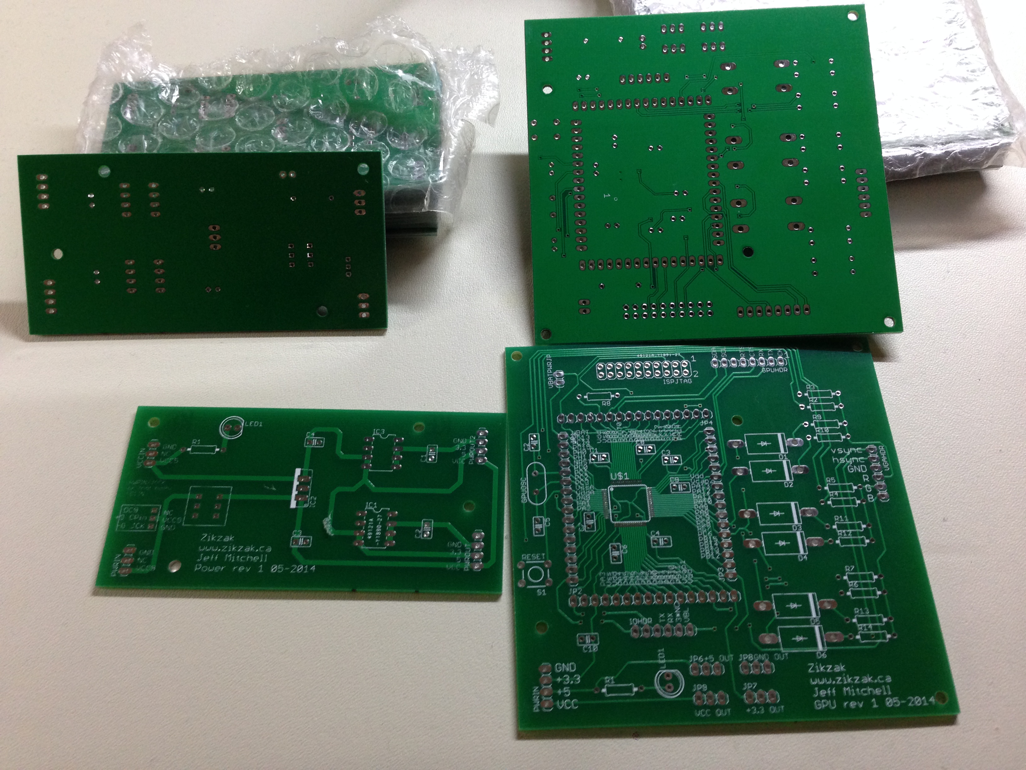
PCB's have arrived and look pretty good; the topmost gpu one had a little scuff on it, but not sure it penetrated the coating so I'll check that later. Sexy stuff!

Here are the front-and-back shots:

https://raw.githubusercontent.com/skeezix/zikzak/master/photos/zik80/gpu_and_power_frontback.jpg

or see the pic here:

gpu_and_power_frontback.jpg

I'll have to do some checks, and start partially populating-and-testing and all that ASAP; can't wait to get some VGA out of this puppy :)

And then onto the base board (ram, cart rom, keyboard, audio, ..), and the cpu adaptor boards (for z80, 6502, 6809, 68000, etc).

So excited :)

jeff
 
Last edited by a moderator:
Awesome.. first tests down.. power pcb.

--> works great!

(only tried one set of outputs, mind; it has space for two TPS7133s (or even a 7150, but that'd be redundant) and I only tried the one for now, but they're a mirror image so I don't see why the other output wouldn't also work. The second 7133 is since they're half-Amp each, and the 7805 can spit out 1A, so doubled up on the output side in case you do need the full Amp.)

One minor defect; I misremembered which contacts on my toggle switch are connected/disconnected when you flip it, so the schematic is hooked up not quite right; these guys I have are 6 contacts, two rows of 3 (like DIP.) Rather than connect across from left-2 to right-2 say, it actually connects all left and all rights, or disconnects them (so the rail is a side, not across.) Clipping off the middle pair of pins, and rotating it, should do the trick (since its square otherwise.) No big deal, and an easy fix if I ever do a rev2 of this.

Setting the o-scope to single-shot and checking the 3 output voltages.. works perfect.

i) Vcc out clearly shows the power supply being an evil bastard; set to 8.8V, but when you hit it.. sometimes you get the 8.8, sometimes (often) you get 12, 15 even 20 V out of the sucker for that first millisecond. Thats what killed all my eZ80's .. its not every time, but often enough; when I tested the bench power supply I didn't catch it. The lesson I learned was to never trust a power supply, and hence these little pcbs :)

ii) 5V out (right out of the 7805) .. works great; when 20V goes in, 5V comes out; sometimes its a vertical climb (very fast), sometimes it takes a ms for the voltage to ramp up, but its still putting out no-more-than-5, which is great.

iii) 3.3V out .. this being the main one! .. also works a treat, out of the TPS7133; 3.3 solid every time, very quick ramp up (nearly vertical), and no spikes. (ie: since the 5V is coming in without weird spikes, this makes sense.)

Should be ideal for feeding the other guys!

jeff

edit: And I know this is all simple stuff to some, but its sure fun to noobies like me ;) yaaaay, a two-IC power supply pcb works, woopee.. but .. awesome, screw those guys ;)
 
Last edited by a moderator:
Hmm .. on the gpu board, as things were getting really hairy in the routing.. a couple of times I ended up implying that the BoB headers were akin to vias; ie: pass through one to connect top and bottom.

I'm wondering now if that was an error.. they may not be plated through (not sure), so may be hard to connect that way. As that was my first complex pcb, I am tempted to re-route it now that I'm more experienced, but I'll keep at it.

(trying to populate one now, and the stm32 is not coming alive; microscope is as always super handy and the IC itself looks very nicely on, so I'm trying to guess out what else could be the cause.)

jeff
 
From elecrow.com:

We will plate all the holes by default. If you need some holes not be plated, please name the non-plated holes layer as PCBname-NPTH.txt
Hope you can get it to work!

ninja'd :)
 
Last edited by a moderator:
yeah, thats what I thought, but never know .. hmm..

I've not fully populated the board; just added the reset button, and that seems to help. GDB seems to do 'something' if I hit reset right when I hit flash, so I suspect the jtag reset circuit isn't quite right. Theres an optional pin I hooked up there, but maybe it needs not to be connected.

I also am using the .1 uF mono caps instead of 4.7uF ceramics and 2.2uF ceramics, so its possibly its flaking out.

Am about to rush out the door (only had 20 mins here, thought I'd see how far I coudl get on the population ;) , but will be back in a few mins. Will hook up the scope and make up a little blinker program on a few pins, to see whats going on. I think it might all be working fine, just with a flaky reset.

Hopefully tomorrow, or worst case Thursday, I can slip out to get the appropriate caps ;)

Will let you know in 30-45mins if she's alive, but I think it may well be!

jeff

FWIW: if I cut power while gdb is attached, it starts to complain. I can actually run openocd in daemon mode, then fire up gdb and it'll break, so I think we're good! find out in a bit.

edit:

We're good!

Finally got 15 solid minutes .. soldered on the GND-out header, checked the code and have some toggles going on PB13; compile with toggles in .. scope shows the activity; recompile without them, reflash, scope shows them vanish. gdb daemon works, attack and step through code is good; vblank indicators are going like crazy.

To flash I have to manually hit reset right when triggering openocd, as apparently the jtag reset isn't working; right after the flash I have to reset again, and cpu does its business.

Will check the schematic .. gotta be somethign a little goofy there, but .. workable for prototype, anyway!

Will solder on the vga-out header, solder together a VGA-port, get the DAC on there, and tonight we should have some VGA action going on :)

Guess I can proceed with layout out the cpu adaptor and base pcb!

edit 2:

okay, reset problem solved; I suspected this might happen a couple months back, but evidently didn't research enough; there is some ambiguity.. the jtag connection doc I was looking at says the reset line is optional (implied that reset coudl be effected another way, perhaps.) I suppose it is optional, in that you can do it by hand ;) Anyway, in the block of JTAG pins there is one called JNTRST or NJTRST depending which datasheet you look at. The other JTAG lines are JTDI, JTMS, etc. Somewhere I got it in my head to connect JTAG Reset to JTRST (which seems reasonable a little), when I had meant to connect it to master reset along with the reset switch. Oops :)

--> Adding a bodge wire (just a jumper on the breakout-pins, its why they're there!) and everything works _perfectly_

So thats an easy fix for rev2.
 
Last edited by a moderator:
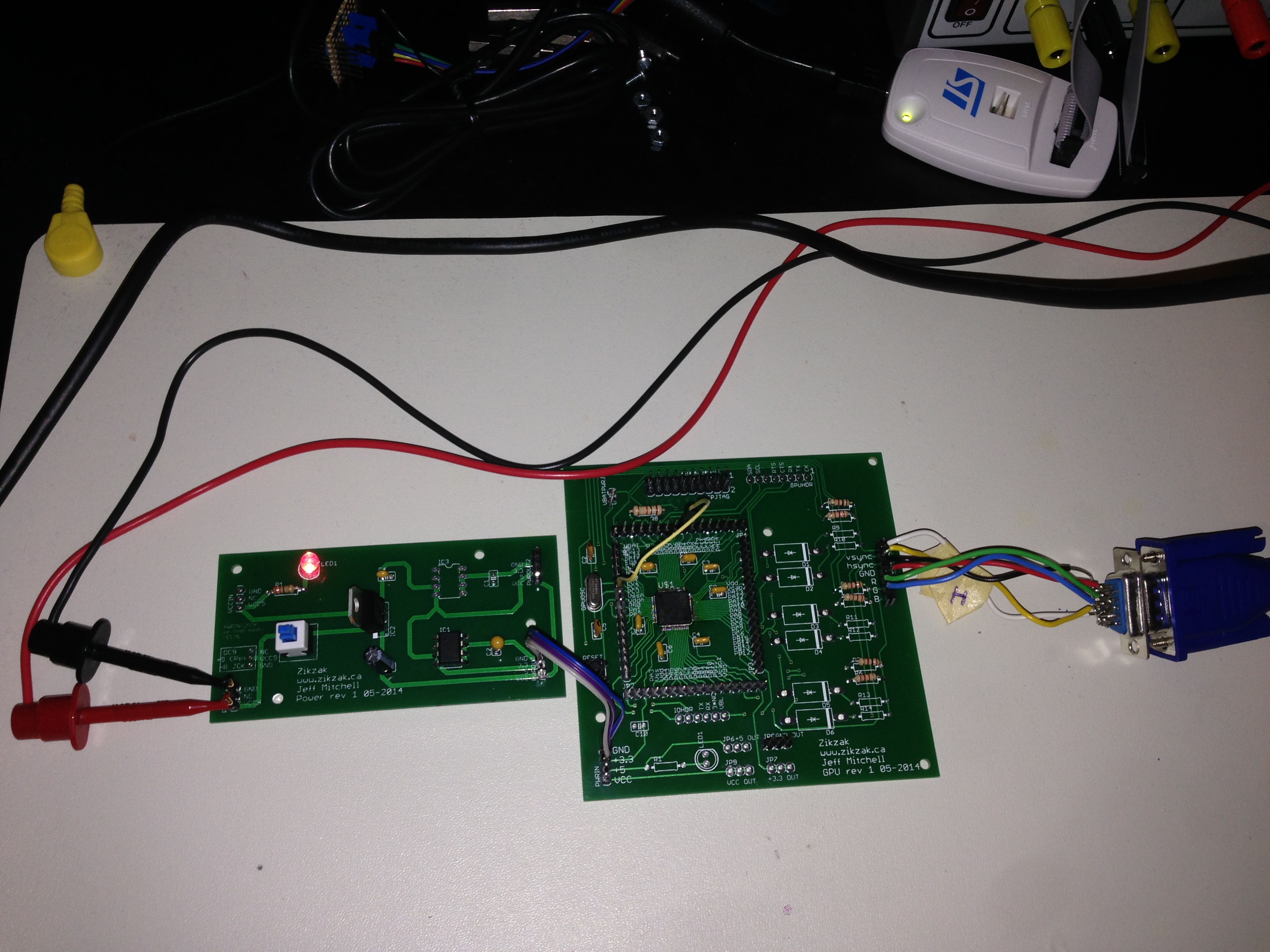
Here we are!

Image showing just the power pcb + gpu pcb + power source + VGA cable, and thats it; no external junk needed:

gpu_proto_r1_running_001.jpg

And the (boring) video of VGa-in-action!

https://www.youtube.com/embed/rh7IwGQg0xc?feature=oembed

The pcb is not fully populated.. didn't add the brightness shades to the output yet (same prototype uber-lame code from many months ago, so doesn't even currently support that), so this is only with 64 colour palette. With the 2 bit brightness shades added, its a full 256 colour palette, woowoo :)

Have to work out how much free time I have, but I think next step is working out a basic lame protocol and hooking up an atmega644 to it and do some really basic demo.. trial out some text modes, some fractal generation, some colour cyling or bouncing Amiga-balls or something, then onto the main base pcb and cpu boards.

I'm so utterly pleased the gpu pcb is working great!

jeff
 
Another late-night post for you :eek: Story of my life..

Astute followers may have noticed that rev1 GPU pcb doesn't have the RAM bus and control lines; the board is fairly tight as-is, and I was hell-bent on getting it done by a (arbitrary) date, so it could get finally sent out and back to me for fun fiddling. Fusk it, I says, wanted to see if the thign would work 'at all' in pcb form, and I've not 'well defined' the RAM bus on the base-pcb and cpu-adaptor boards yet. (Its a fair number of pins.. most of the little 8bit cpu's can't address a lot of RAM anyway, but the bus for zikzak is up to what, 20 or 21 max pins for addresses (due to cart limits, you can go more if you're skipping using the default cart system), plus the 8 data pins, plus some control lines (plus the other lines.. power, flags like vblank, some misc gpios, etc and so on.) So add another 16+ for address, 8 for data, say 8 for control and flags.. thats another 32 points of header on there, and all the routing to make it happen. Later, baby :)

Anyway, so that left two slower but easier to prototype with GPU control systems, and could still proto the RAM bus on the break-out pins. (And if you notice, the STM32F405 that I'm using is the 64pin one, which may not be enough pins to run the RAM bus anyway, depending how we limit it.) For the full RAM bus supporting board, I might make it a slightyl larger board, and use the 100pin QFP version of the chip; more pins to play with, but also means another 32 header pins for breakout, and the 32+ pins for the RAM bus. Bleh :)

Of interest.. the rev1 GPU pcb supports serial and i2c control (or others via BoB headers.) One serial (usart2) is assumed to be console and is wired to the IO header (and I feed that to an FTDI chip, to talk USB to PC.); usart1 is in turn wired to the GPU interface header. IIRC, usart1 is a much faster one as well.

The rev1 GPU pcb I figured could be useful for a general display pcb (or of course, as a general stm32 project board of course.)  A single serial TX pin from some random chip, over to the gpu board heree and voila, we've got easy control VGA text and graphics modes. I may use it on my robot car for the LCD driver, for example, instead of the lame little 2 line LCD we all use.

Now, working with the GPU in serial/i2c makes it more like a opengl style driver; simple interface, scene graph on the gpu board, talk to it over the wire.

With the full RAM bus, you cna do bitmapped graphics in RAM and have the GPU just display it (sweet!), or route your protocol throgh RAM (queue up an array of instructions in RAM and have the GPU just iterate it; like sprite listings, etc.) This is very much more like old arcade boards and such. Worry about that for rev2, once I've nailed it down in the other prototype boards.

I really do like the STM32 pin routing options; usart1 RX and TX can be represented on GPIOB pins 6, 7 or whatever, and also on GPIOA on pins 10,11; just pick where you want the alt-functions to go, and thats that. Brilliant! Sure makes layout out the pin choices more interesting, and easier .. routing hard? Send the Alt-func over the other side instead!

--

Anyway, got an atmega644 with RX/TX hooked up to the GPU protocol line; GPU console is to FTDI to PC.

So now the atmega can drive the GPU board, and GPU board dumps all the requests to the PC for verification.

... now I just need to write a lame little protocol and the framebuffer manipulation stuff. Brute force ftw, time is tight, but goal is both a text mode for a dumb terminal, and some basic sprite handling to make a space invaders light, or something :p Oh, need to tweak the VGA timings quite a bit; the values I'm using now were for the F2 instead of F4, at a slightly different clockrate, so it still (miraculously!) renders to VGA but blorps out a bit depending how the monitor is feeling at the time, since its not quite hitting the timings right. An hour or two on the scope adjusting things should get that sorted out.

.. fun :)

jeff
 
Back
Top