Hardware: Difference between revisions
No edit summary |
No edit summary |
||
| Line 22: | Line 22: | ||
=== [[CPU-Board|CPU Board]] === | === [[CPU-Board|CPU Board]] === | ||
[[Image:Moduleboard_traces.jpg|thumb|PCB traces | right | | [[Image:Moduleboard_traces.jpg|thumb|PCB traces | right | 320px]] | ||
{{:CPU-Board}} | {{:CPU-Board}} | ||
=== [[Displayboard|Display board]] === | === [[Displayboard|Display board]] === | ||
[[File:Display pcb unpopulated prototype.jpeg| | [[File:Display pcb unpopulated prototype.jpeg|thumb|320px|right]] | ||
{{:Displayboard}} | {{:Displayboard}} | ||
| Line 45: | Line 45: | ||
== [[USB]] == | == [[USB]] == | ||
[[ | [[Image:Pyra prototype back.jpeg|thumb|320px|right]] | ||
{{:USB}} | {{:USB}} | ||
| Line 59: | Line 59: | ||
{{:Bluetooth}} | {{:Bluetooth}} | ||
== Optionnal 3G module == | |||
=== [[Modem]] === | |||
{{:Modem}} | |||
=== [[GPS]] === | |||
{{:GPS}} | |||
== [[Audio]] == | == [[Audio]] == | ||
Revision as of 09:00, 8 August 2017
A mess for now. Moving from Main page.
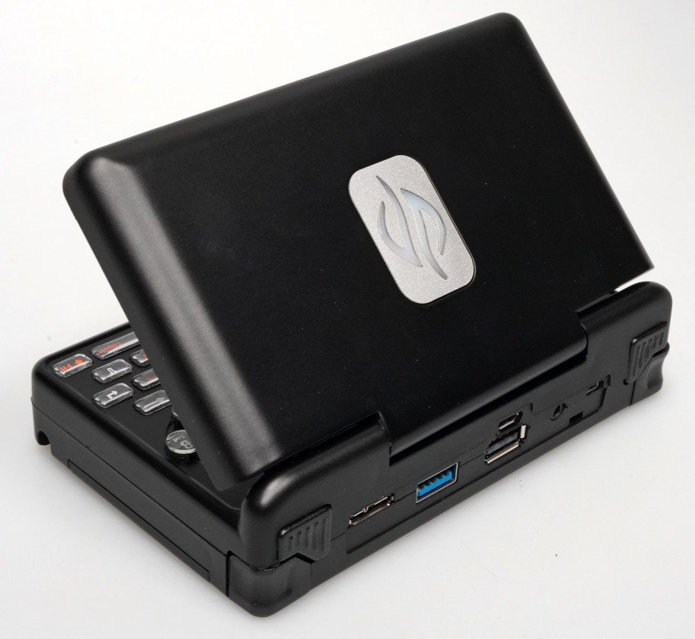
Case
General case info
- Dimensions 140 x 84 x 29 mm
- Poly-carbonate (PC) plastic (very strong)
- Molds are made for PC, so PC pellets are needed
- Color is be mixed into the plastic itself
- Cases are then coated to provide final color and better finish
Production colors
- Current production color are Black and Dark Chrome
Prototype colors
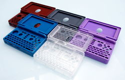
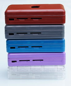
- Prototype Colors [1]
- At that stage it was decided that one color will be definitely Black [2].
- All RAL Classic Colors should be easily available[3].
-
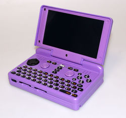
First Prototype in Clear Case
-
Some assembled Prototypes in Comparison
-
"Gunmetal" Grey Prototype Case
-
Violet Prototype Case
-
Some Prototype Colors in Comparison
-
Some Prototype Colors in Comparison
Blender file
- The Blender file of the case can be used to make mods or renders of the real thing.
Injection Molded Plastic
- The default injection molded case is produced in Greece.
- Based on the Pandora case with fixes to, among other things, battery compartment width.
Coating
- It was decided to coat (paint) the case to provide a better finish Ref
- Without this, case show reflection and minor defect
Development cases
- Early Cases where 3D Printed.
- First (Injection Molded Plastic) prototype Cases needed a lot of Fixes (such as Fixing the Gap at the Front).
Boards
The pyra use a multiple boards design.
Mainboard
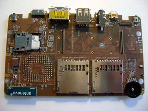
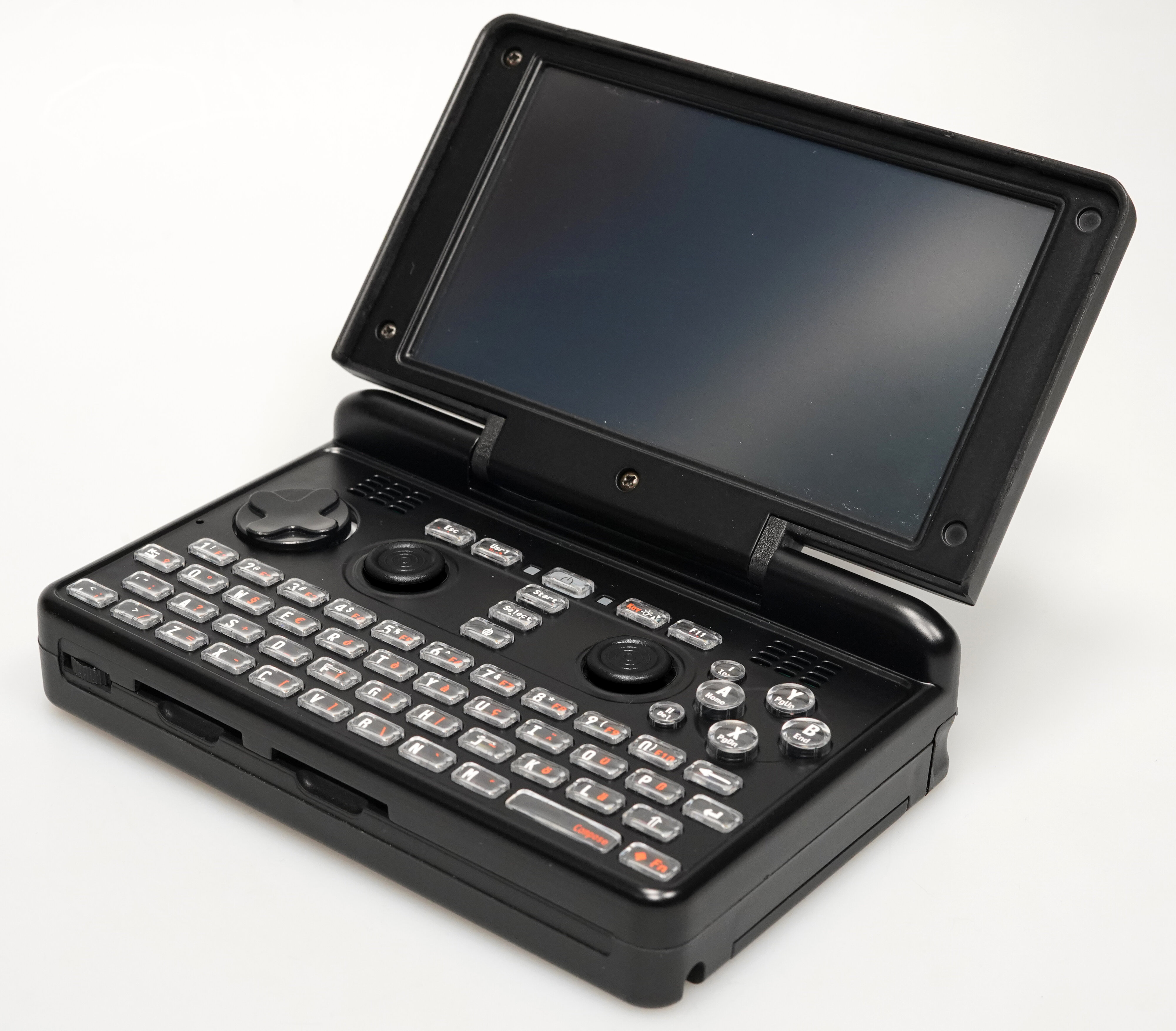
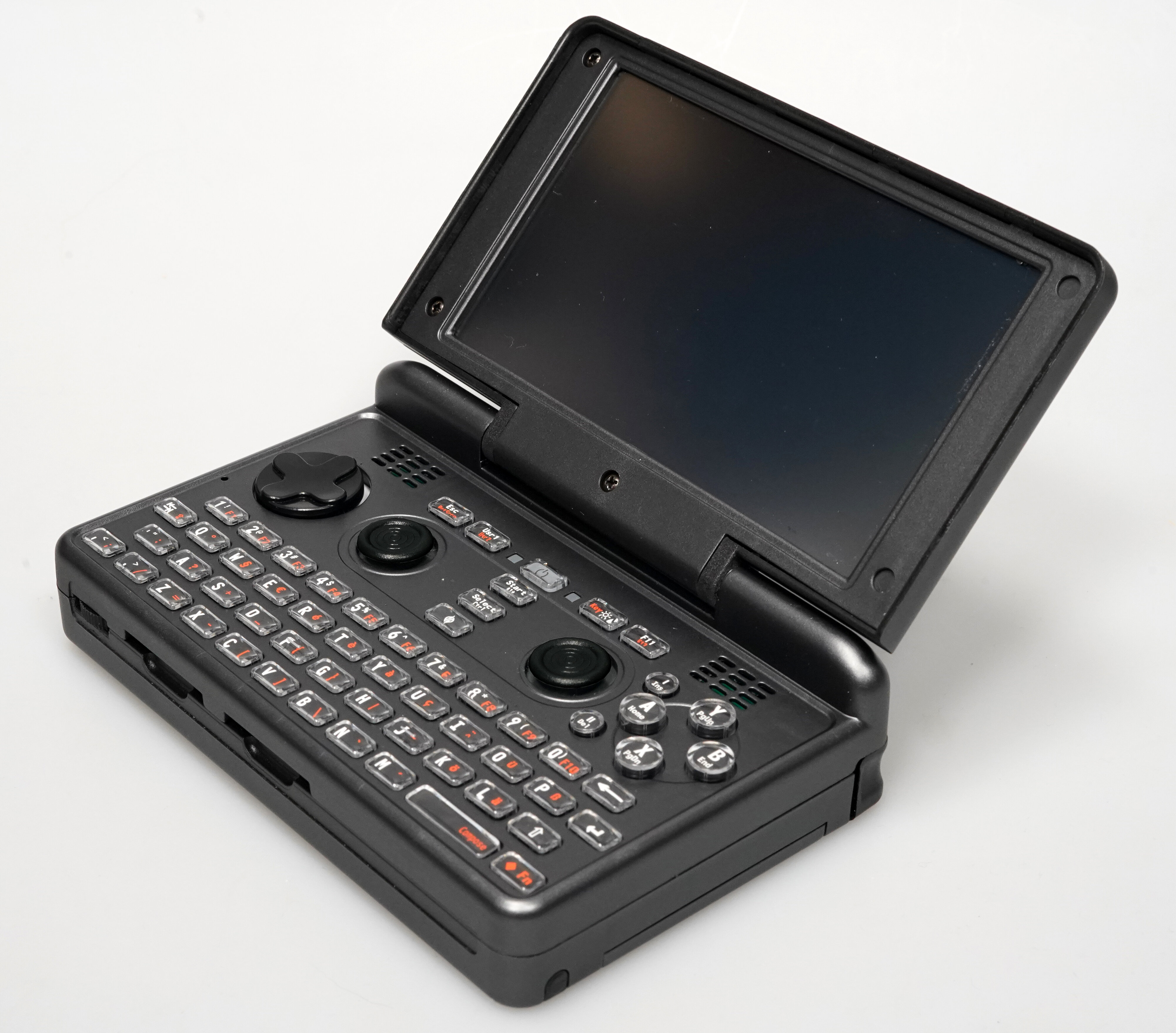
This is the largest PCB in the Pyra, with a wide range of different functions. It could be compared to the motherboard in a traditional desktop computer, with the addition of a keyboard and gaming controls on one side. Display-support hardware (the Displayboard) and the processor itself (see CPU-Board) are each on separate PCBs.
The Mainboard includes the following hardware:
- Nubs
- Keyboard
- Connectivity
- Storage
- Rumble
- Optional modem
CPU Board
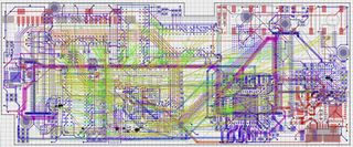
The board with the CPU, GPU, RAM, and eMMC memory which detaches from the Mainboard. Depending on various commercial and technical considerations, new CPU boards may become available to upgrade existing Pyras.
Display board
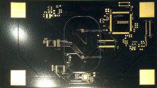
- The PCB that is behind the screen, connected between the Display and the Mainboard
- Carries the Touchscreen Controller
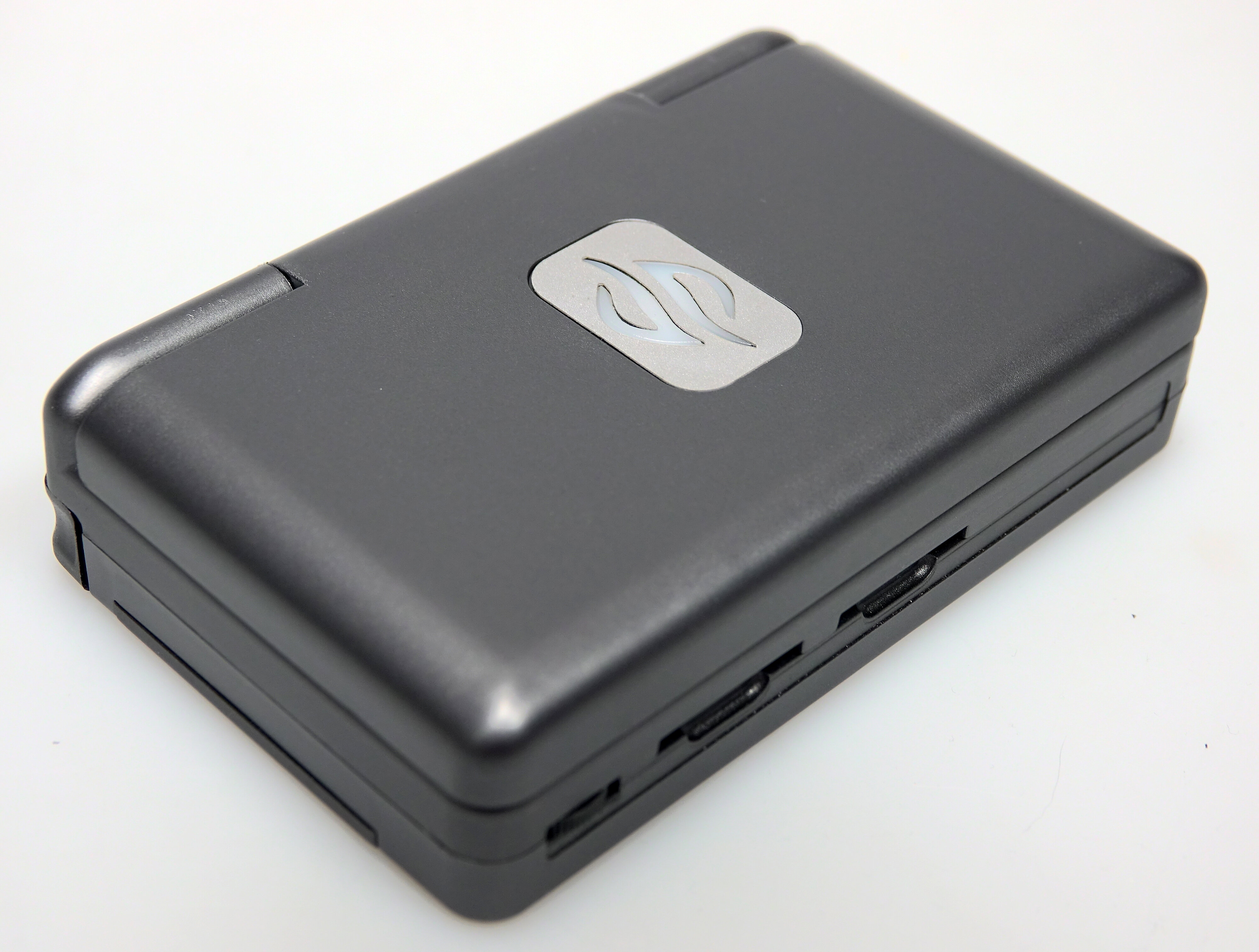
- Also carries two RGB LEDs that shine through the logo on the back of the lid. See: LEDs
Display
LCD screen
This is a 720p, 8-bits-per-channel LCD with a resistive touch-sensitive layer suitable for use with fingers as well as a high-precision passive stylus. Multi-touch detection is also possible to a limited degree.
The market for small LCDs is largely driven by smartphones, making it prohibitively difficult to source a native landscape display. As a result, the Pyra uses a portrait display, with a dedicated video rotation chip interfacing with the CPU/GPU
Tiler
The tiling and isometric lightweight engine for rotation (TILER) resides in the Memory Subsystem of the OMAP5 and Manages the virtual address, data, and byte-enable to match the requested 0-, 90-, 180-, or 270-degree orientation in a tiled 2D addressing space. Previously there was only an slow (because of Bugs) Driver Available, thus the decision above. Later a Community Member (Zmatt) wrote an new Driver, which performed perfectly.
The TILER is needed for rotation because the naive way of rotating a framebuffer (swapping X and Y coordinates) would give poor performance with modern DRAM, where accessing data from a different row of 8kB - which would be every few pixels in a simple rotated view - is significantly slower than accesses from the same row. Using "tiles" significantly improves this.
To use TILER in 2D mode from user-space, the generic DRM_IOCTL_MODE_CREATE_DUMB ioctl must be replaced with the OMAP-specific DRM_IOCTL_OMAP_GEM_NEW ioctl, with the OMAP_BO_TILED_32 or OMAP_BO_TILED_16 flag set depending on bpp. The stride must be a multiple 4096 bytes. Setting the rotation property of the plane should then use the tiled buffer for rotation. Legacy framebuffer code that accesses /dev/fb0 should be rotated automatically with the current TILER patches. tiler_rotate_shim can also perform the ioctl transformation to existing code, like the PowerVR drivers, using LD_PRELOAD.
Video Output
The Pyra has a digital video output supporting HDMI 1.4a, HDCP 1.4, and DVI 1.0 which can be used independently of and at higher resolutions than the built-in LCD. (Confirmation Needed)
It uses a 19-pin HDMI Type-D micro connector.
Main system chips
CPU
The OMAP5 (OMAP5432) is the SoC (System on Chip) of the Pyra. It's designed by Texas Instruments and fabricated by UMC on their 28LP process. It resides on the CPU-Board, with these specifications:
- 2x ARM Cortex-A15 @ 1.5Ghz with NEON SIMD
- 2x ARM Cortex-M4
GPU
This is on the CPU-Board, as part of the OMAP5 SoC, so has a chance of being upgraded in the future but it cannot be changed separately to the CPU. Unlike a discrete GPU, each block reads/writes main system memory and final video output is done by the TI DISPC display controller block.
- PowerVR SGX SGX544-MP2
- Vivante GC320 2D Accelerator
- HDMI Encoder: HDMI 1.4a, HDCP 1.4, and DVI 1.0 Compliant" [4]
RAM
Dual Channel PC DDR3L 532MHz:
USB
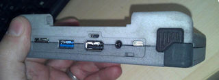
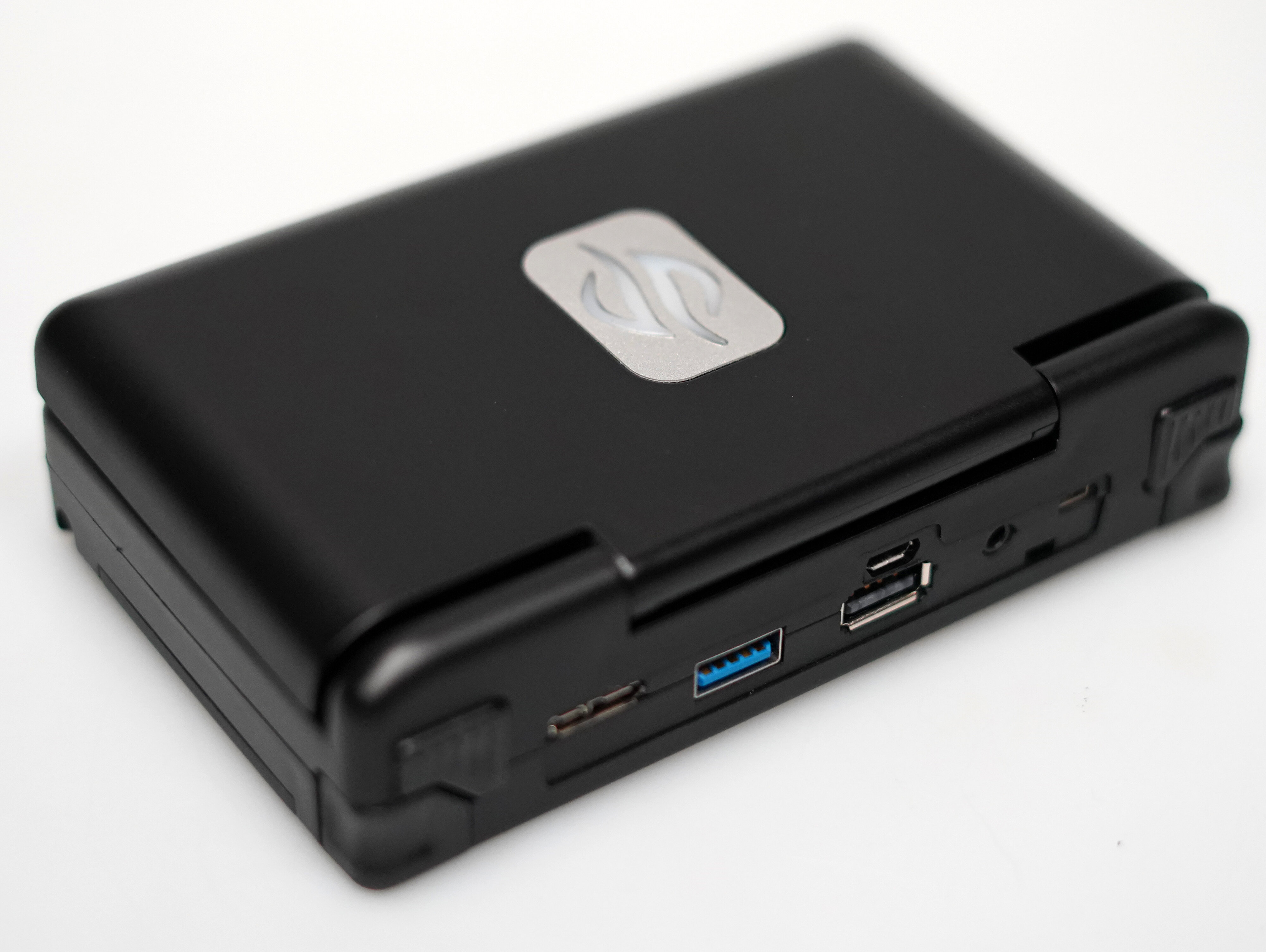
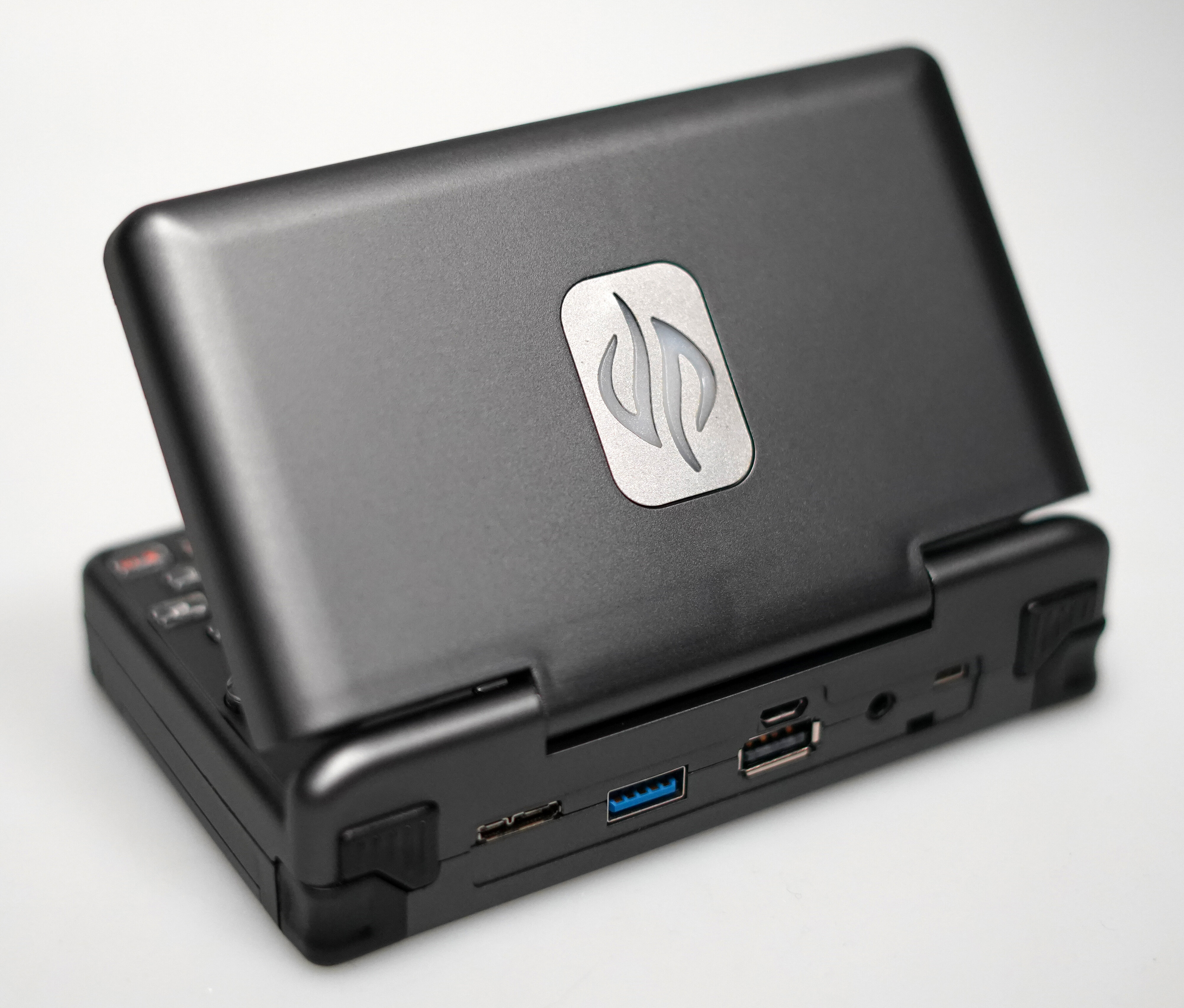
The Pyra has four USB ports, as detailed below.
For our purposes:
- "USB2" means "capable of Low, Full and High-speed"
- "USB3" means "capable of low, full, high and super-speed"
- "OTG" means capable of operating in either host- or slave-mode.
Full-size USB2 Port
This is a straightforward USB port as found on many desktop PCs. I can be used for keyboards, mice, USB memory sticks, network adaptors and many other things (subject to driver support)
Full-size USB2 Port with eSATA
This can be used as a simple USB2 port as above. Although this uses a blue Connector designed for USB3 Ports, it is not capable of USB3 (with the current CPU-Board). The additional pins are used for (e-)SATA Lanes for to an Adapter.
See Storage for more details.
Micro-USB3 OTG Port
This can be used much like the full-size USB2 ports, but at higher speeds and with the obvious requirement for a passive adaptor when using most peripherals. It can also be used to charge the Pyra (either from another computer, or a mains adaptor) and to operate as a USB slave. The Pandora has software allowing it to operate as a USB mouse, joystick, keyboard or SD-card reader in slave mode. It is expected that similar software will be available for the Pyra.
Serial-via-micro-USB2 Port
This is not a general-purpose USB port (as a result of limitations of the SOC) but can be used in two ways:
- Charging the Pyra while the primary microUSB3 port is in host mode.
- Monitoring the Pyra using another computer (Serial output from the Pyra's processor, via a built-in Serial-USB translator, with the Pyra as USB slave)
Charging
The Pyra will charge from a standard microUSB2 cable, connected to a standard 5V USB2+ charge brick. This can either be plugged into the USB2 section of the Micro-USB3 port, or the serial debug and charge Micro-USB2 port.
Sample of potentially official charger
Radio
The Pyra's Wifi and Bluetooth systems are both provided by a Texas Instruments WL1837MOD
WiFi
This supports 802.11abgn on the 2.4GHz and 5GHz bands.
Max data rate (40 MHz channel and 400 ns GI): 150Mbps
Real conditions by TI: 80 Mbps (TCP), 100 Mbps (UDP)
Bluetooth
This supports Bluetooth 4.1[5] and BLE.
Software support should be available for (at least) file transfer and A2DP audio. This means all standard Bluetooth headphones and speakers will (probably) work.
Optionnal 3G module
Modem
The Modem will be a PLS8-E (EU Version) or PLS8-US (US Version). It provides GSM, LTE and GPS. SMS and voice is supported and tested, however it will fall back to 2G for voice on most networks. There's a CPU-GPIO controlled FET switch to disconnect the whole modem from power so you don't have to rely on the closed-source modem firmware. Also, there's a current sensor to detect if the modem is doing unwanted things. [6]
Antenna
The Antenova A10340 as seen here is listed with "Antennas Calvus SMD GSM850/ 900/1800/1900/WCDMA"
GPS
The Modem also supports GPS (optionally Cell-Tower assisted GPS[3]) and GLONASS. So you need to buy an Modem Unit if you want GPS.
Audio
ADC/DAC
- TWL6040 integrated 4-channel DAC, 2-channel ADC, headphone and speaker amp, microphone preamp, and vibration driver using dedicated McPDM interface for communication with the OMAP5
Jack
- 3.5mm headset TRRS (stereo audio and microphone) connector with automatic switch to go from OMTP to CTIA as seen here
Hardware:
- TS3A227ERVAR - Autonomous Audio Accessory Detection and Configuration Switch
- Detects 3-pole or 4-pole audio accessories (headphone / microphone) and configures internal switches to route the signals accordingly.
- FDV301N - N-channel MOSFET used to generate "PLUGDET" signal when headphone jack is inserted.
- CUI SJ-43516-SMT-TR - 4-contact, 3.5mm audio jack with tip and ring switches
Volume Wheel
- Potentiometer to GPIO input in SoC, 10-Bit Resolution (allows software override of volume control)
Microphone
- Microphone located at the left edge between keyboard and D-pad.
Speakers
- Stereo speakers in base with tuned cavity behind them as per manufacturers' recommendations.
Batteries
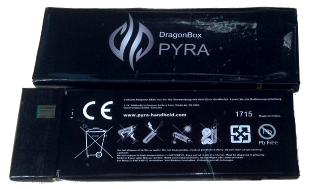
Features and specifications
- Battery is easily removable and replaceable (though no hot swapping?)
- 6Ah Li-Po battery (at a nominal 3.7V, for approximately 22Wh)
- Can be charged in the Pyra using either of two microUSB ports (one carries USB3.0 otg, the other serial debug data)
- Includes 103AT NTC (10K thermistor) for thermal safety on middle / ground contacts
- When it is plugged in, it works like an offline UPS.
Battery life
- Everyday work load: 8 hours (without any power management features, tested on prototype April 2016)
- Everything on (Bluetooth, WiFi, etc.): TBD
- Display off, audio on: TBD
- Suspend mode (display off, audio off, CPU running): TBD
Charger
The Pyra will charge from a standard microUSB2 cable, much in the same way as any other (non-apple) portable device made in the last few years.
Sample of potentially official charger, but as USB power warts are so common, it has been decided to not offer one in the Pyra box, to reduce waste.
See also USB
Hardware
- BQ27421YZFR-G1D - I2C (addr 0x55) Battery monitor - System-Side ImpedanceTrack™ Fuel Gauge With Integrated Sense Resistor
- Used to measure "VBATT"
- AVX 009155003201006 - Battery Contacts 3Way .4um Ht=3mm 3A 2.5mm Pitch Rdc Size
The battery itself is custom designed and manufacturerd specfically for the Pyra project.
Storage
The Pyra has a range of options for data storage.
Internal eMMC Memory
Solid-state memory with 32GB capacity on the detachable CPU-Board, where the default operating system will be installed, and where you can put games, applications, and other content.
SD Card Slots
The Pyra has two full-sized SDXC card slots, externally accessible, via an MMC interface (not USB).
Hardware:
- FPS009-2960-0 - 2 x SD Card and MMC Reader - Push / Push (Reversed Type)
It also has a microSDXC card slot behind the battery, which shares with the internal eMMC memory the same interface to the SOC, but which is controlled by a software-managed switch. This theoretically allows both to be accessed near-simultaneously, albeit with a decrease in throughput.
Hardware:
- Wellco SMSN16-X0-2X00 - SIM and microSD card connector
eSATA via Adapter
eSATA support comes via an active Adapter which plugs into a USB port, but it is not a USB-to-eSATA adapter -- the additional pins that would normally be taken up with USB 3.0 signalling have been used for SATA signals. This allows far higher transfer rates than would be possible over USB. In addition, should a SOC become available in future with a second USB 3.0 interface, it could be routed through the existing connector to provide a dedicated USB 3.0 host port.
Hardware (duplicated from the USB page):
- Molex 48393-0003 - USB 3.0 Female Type A Connector
- USB 2.0 data pins connect to "HOST1-D" pins of the CPU module
- USB 3.0 data pins connect to "SATA-RX" and "SATA-TX" pins of the CPU module
Miscellaneous
Other data storage options:
- Two full-sized USB 2.0 host ports, can connect flash drives etc.
- One microUSB 3.0 port making use of the optional otg (host-peripheral) functionality (can also be used for charging)
- One SIM card slot (behind battery, on models with WWAN hardware)
LEDs
- Two independent RGB LEDs behind the logo on the back of the lid
- Two RGB LEDs on near the power button
- One RGB LED underneath the power button
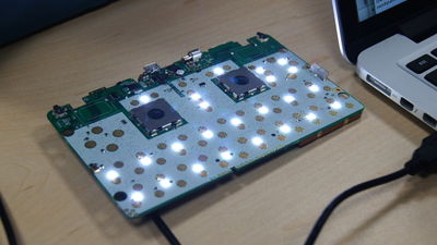
- Several white LEDs used to backlight the keyboard (These can be controlled in groups, see video for demo)
More
- ↑ https://pyra-handheld.com/boards/threads/first-newspost-coming-from-the-pyra.77152/page-2#post-1370826
- ↑ https://twitter.com/EvilDragon1717/status/614405797783584769
- ↑ However The Cell-Tower Data needs to be Manually fed to the Modem by the Host
