Disclaimer: The contents of the package are at least eight months old as of December 2017. During this eight months there have been numerous announcments of improvements and fixes. Therefore some of the facts / opinions / questions expressed in this post may not be relevant for the final product.
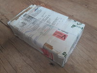
I got the package from the post office on the 18th.
I expected a lot bigger box, it's only 235 x 145 x 65mm.
It seems the box was reused for at least part of the tour.
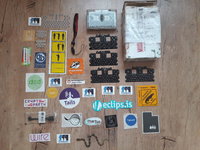
Despite the small size, there are a lot of things cramped inside:
- an assembled keymat test unit
- 7 addtitional keymats
- a USB 2.0 OTG cable
- a wrist strap / lanyard
- 24 stickers
- a plastic snake

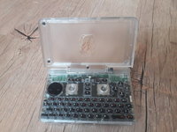
The assembled unit consists of:
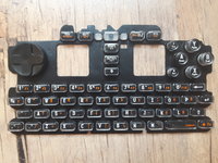
- a keymat with d-pad
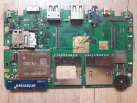
- a populated V5 EU 4G mainboard
- most of the injection moulded parts
- a barrel hinge
- most of the screws for holding the case parts together
- rubber stands on the bottom of the case (yay for not covering any screws with these

)
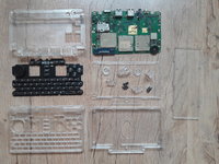
What is missing from the assembled unit:
- touchscreen
- display PCB
- LCD cable
- logo plate and light diffuser
- screw covers for lid screws
- magnet for lid closure sensor?
- CPU board
- stylus and stylus holder
- battery and heat shield
- heat conducting pads to go between the mainboard and CPU board?
- heat conducting strip and heatsinks
- speakers and sealings
- a screw from the base of the unit

- production stickers
- something I probably forgot
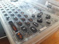
Backspace stuck
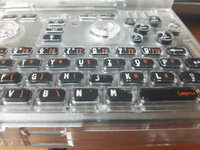
"J" stuck
I like the keymat of the assembled unit in general. It's better than the additonnal (historical) keymats included in the package. The rounded keycaps feel good compared to the flat ones. Tactility is acceptable, I expected a little bit shorter key travel and harder pressure point. I can easily press three buttons at the same time with my thumb, but it's not difficult to press them individually, so key separation is OK. I experienced ocassional key stick, for example on the "J" and backspace keys. As mentioned before, shoulder buttons are inoperable in this prototype. It seems ED put a lot of work into refining the keymat during the last eight months, and I trust it to be as good as pracitcally achievable. After all, the mere existence of a QWERTY keyboard on a handheld device is a big plus. Let alone a backlit QWERTY keyboard!
I think the keyboard layout is a good compromise. Nevertheless, I will look into ways for substituting some letters. I suspect this has to be done at three different places for the bootloader, the console and the GUI. For the Hungarian language, I have the following substitutions in mind: Y -> Z, Z -> Y, ä -> ő, ß -> ű, à -> á, ç -> ú, è -> ó, § -> í.
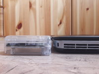
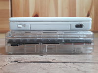
The thickness of the device is comparable to a full size laptop, 36mm including rubber stands. However, the device can be quite comfortable in the hands. BTW, how is this thing meant to be held?

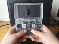
In the 180° open position, if I hold it with my index and middle fingers at the bottom of the device, and support it from the direction of the SD card slots with my ring and little fingers, the keyboard area and the game controls are easily reachable with my thumbs, but I can't reach the top row (beginning with "Esc") with my thumbs and the shoulder buttons with my index fingers. This position is comfortable for typing, but I lose chorded modifiers on the shoulder buttons.
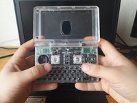
With index fingers on the shoulder buttons, middle and ring fingers at the bottom, and little fingers supporting, the top row and the game controls are easily reachable with thumbs, but the keyboard area outside of the rectangle defined by the keys "2", "A", "L" and "0" is not so easy. This position could be a good compromise, but the uncomfortable feeling resulting from forcing my little and index fingers away from each other drives me nuts.
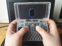
With little and ring fingers at the bottom, index (and maybe also middle) fingers on the shoulder buttons, and my palms supporting at the corners, I can't easily reach the keyboard area with my thumbs. This position may be ideal for gaming. To be able to put four fingers on the four shoulderbuttons, I had to move the lid from the 180° open position.
I'm more interested in typing on the keyboard, than in gaming controls. The idea of modifiers on shoulder buttons is clever, but I couldn't find a comfortable position for easily reaching both the keyboard and the shouder buttons. Well, I guess my hand size or proportions are not in line with the German average

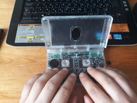
I think the device is too small for ten-finger typing when placed on a table, but six-finger typing seems OK. The hinge is acceptable, I think there is enough friction for holding a screen in a vibration free environment. As mentioned before, it clicks in place at the closed and the 180° open position. IIRC the hinge is another area that was being worked on during the last eight months.
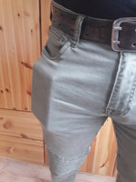
Thanks to rounded edges and corners, I can easily put the device into the pockets of my tight-fitting pants, but moving around this way is not comfortable. As someone suggested, cargo pants and fanny packs may come back into fashion

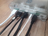
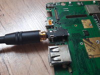
The connector is on the edge of the PCB. 3,5mm jack plugs in all the way...
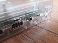
...but the connector doesn't sit flush with the plastic case
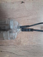
Ouch
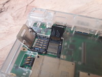
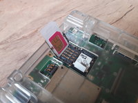
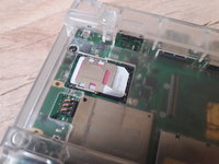
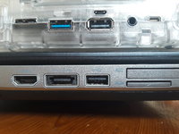
USB host ports upside down?
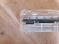
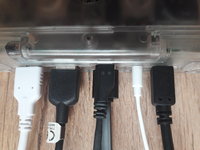
All external electrical connections seem to function as intended, and plugs don't get in the way when plugged in. The 3,5mm TRRS jack socket may be close to the limit regarding depth of installation inside the plastic case. I was able to fully plug in a smaller plug, but I had no luck with a larger one, as the plastic case is blocking the plug. The USB 2.0 micro B socket (console port) is only usable with a slim plug when the neighbouring USB 2.0 A socket is in use with normal size plugs, but I think this is the intended behaviour. The SIM part of the mini SIM / micro SD combo port is a bit hard to open / close with bare hands (or fingernails

), but much easier with a little tool. BTW I was a bit surprised about the mini SIM slot, I expected a micro. Now that I think about it, this is the best solution as bigger sizes are doable with a cheap adapter in seconds, but making a SIM card smaller can give you headache. Oh and by the way, USB A sockets seem to be upside down

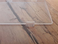
I accidentally cracked one of the clips of the battery cover. This part is a very tight fit on this unit. This a known problem, already confirmed to be fixed.
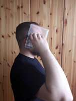
Somebody remember Nokia N-Gage?

Typical reactions from friends and colleagues:
- the device is very thick
- nubs feel great
- looks funny when held to the ear (taco-talking)
- price is ridiculous
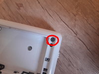
Grr no case mod today
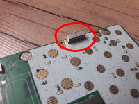
Lid closure sensor?
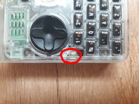
Is this the hole for the mic?
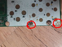
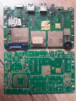
What is connected to the vias on the right?
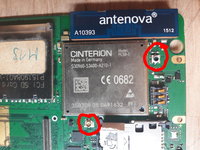
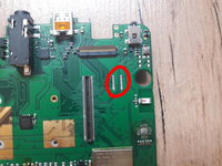
Solder pads for 20p B2B connector
Infinite energy?

Qusetions. Maybe someone can answer these.
- Currently I have a Nintendo DS lite at my disposal and wanted to try a hinge mod on the Pyra, but sadly I have no tool to open the DS. I tried some improvised tools but failed. Do you have any suggestions how to open it? Is it tri-point or tri-wing screw head? Right-hand or left-hand thread?
- IIRC the lid closure sensor is a Hall-effect sensor. This requires a magnet in the lid, right? How is the magnet going to be held in place?
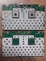
- Where is the internal microphone? Is it the component with the tiny hole on it, under the hole in the plastic case near the D-pad? The two holes don't line up. Is this intended? Does anyone have a sound sample recorded with the internal microphone?
- There are two U.FL connectors near the modem. According to the published schematics, these are connected to the modem. Can these be used for connecting external antennae or are they only for test / calibration purposes?
- According to the published schematics, in addition to the two hundred-pin connectors, there is a twenty-pin board-to-board connector between the CPU board and the mainboard. Among other signals, there is a single lane of MIPI CSI routed through this connector. To be precise, the symbol representing the twenty-pin connector is crossed out in the mainboard schematics, but not in the CPU board schematics. Does this mean that it is omitted during assembly? Is there a hacker-friendly solution on one of the boards for accessing CSI signals?
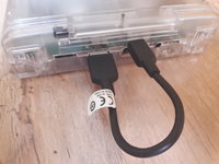
- If I'm not mistaken, charging is possible through both of the micro USB ports. According to the schematics, if I connect a charger to both of them at the same time, it prefers the USB 2 micro B (console) port. But what happens if I connect one of the USB2 host ports with the console port? Infinite energy?

- One of the USB2 host ports have a USB3 connector, with SATA2 signals connected to the additional pins. What happens if I connect a USB3 device to this port?
Finally, I want to say thanks to EvilDragon and team for all the hard work. I wish you success for the project. The device you're building and the way you do it is truly one of a kind.
Friction between volume wheel and plastic case
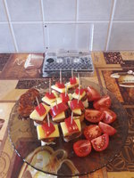
Feeding Pyra

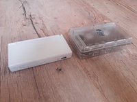
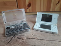
Comparison with Nintendo DS lite
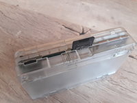
SD card is upside down
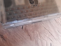
Sits flush
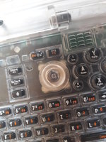
Nub is cracked
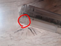
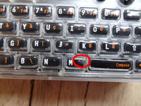
Air bubble?
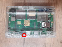
OK guys, who lose this screw?

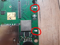
WiFi antennae
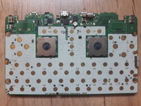
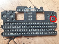
Apparently the D-pad needs a vent-hole

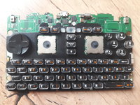
ps: Dou you have any questions or photo requests?
Also: MOAR NEWZ!!!


