I Need To Know The Serial Pinouts; Rx, Tx And Gnd


glossywhite

Still Fresh
Joined
Nov 26, 2009
Messages
94
Hi guys. Okay, making a simple request for all you great people - don't need pointing to any messy Wikis with back-to-front pin numbering etc, or having diagrams drawn in ASCII please - I simply wish to know which pins are serial RX, serial TX & GND?. Here is a nice clear photo of the connector (larger sizes @: My Flickr):

4166236886_8484633d61.jpg


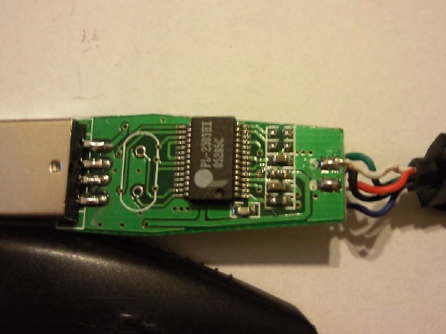
I want to do a boot log of the Wiz, and I am connecting the pins directly to a modded PL-2303 usb dongle (used to be a Nokia DKU-5 data cable):

75967659_1.jpg


94_1233508152.jpg


...which I am using for bootlogging of a BT Home Hub and also a Netgear router, so I know it works (3.3v TTL). I presume the Wiz uses 3.3v TTL logic levels?.

Thanks.
 
You need a one-time boot log, or you fiddling with kernel settings or somethifn so expect it to change?

ie: Someone with a serial / BoB could just post the bootup log and save you the work ;)

jeff
 
skeezix said:
You need a one-time boot log, or you fiddling with kernel settings or somethifn so expect it to change?

ie: Someone with a serial / BoB could just post the bootup log and save you the work ;)

jeff

I am just curious - I have been examining various GNU/Linux-based router bootlogs, by connecting to the serial port on their PCBs. I love knowing what is going on inside my gadgets, hence my request here.
 
Last edited by a moderator:
Surely all the 5v DC inputs from the USB to the wiz (red) are connected together *inside* the console, so I can free up two of the three +5vdc pins which are strapped together here, and move the pins to the serial (com) RXD & TXD locations?. Also, does there NEED to be *two* ground pins, or can I borrow one of those, also?. In my experience as an electronics engineer, there is always a common ground plane on the PCB, to which all ground points are connected, unless there is a good reason not to - in this respect, whichever pins need to be grounded, will be grounded *internally* - you only need to connect *one* ground wire coming from the cable, and they will (surely?) be commoned *inside* the console, no?.

4169254562_3047e1d5fa_o.jpg


4169253876_ef90f4283e_o.jpg


New info (I think :) ):

4171885648_ed109b5bee_b.jpg


The internal view of the GP2X "Wiz" ext connector. Pins 12 & 19 which are +5v in (loading) are shorted together internally, and pins 21 & 22 which are ground, are shorted together internally also.

This allows us to free up two pins inside the standard supplied USB cable, and move them to pins 13 & 14 (RXD & TXD) for serial port monitoring.

### This is *not* guess work - I am a qualified electronics engineer, and I guarantee you that I have triple checked everything shown here, and it is correct to the best of my knowledge. ###


### [EDIT] ###

Used the spare pins from +5v & GND, and moved them to RXD and TXD, and tapped a GND off as well. I now have a combo Standard Wiz/Serial cable (the other end of the serial line is connected to an old Nokia DKU-5 cable, which contains a "Prolific PL-2303 usb to serial convertor".

Nice ;) and easier than typing in "termula"!
 
Back
Top