HW Hack: Keyboard light


cube48

Member
Joined
Oct 6, 2008
Messages
288
Location
Bohemia
Website
www.48.cz
When using Pandora in the evening, I'm finding my self quite often in the situation when I have to move closer to the light source to type something on the keyboard. Yes, I know that I can bend the LCD into 90° position to enlight the keys but that's not comfortable to type and it's unnecessary stress for the hinge.


I'm currently in the planning and parts collecting phase for this hack. Having relatively clear idea where to place the LED (or two if needed) - if you fully open the lid, put your finger on the number 6 key ... in the spot where your nail touches the lid is a chink of the two LCD encapsulating parts. I intend to drill or mill there an appropriate hole for the LED of my choice and direct it to keys in this fully open position of the lid. I've ordered hi-bright by CREE and one more classical LED. Will see what suits better to my eyes and if the CREE LED is not getting hot.


My original idea was to take the power somewhere from the MB, limit the current if needed with resistor and put tiny switch into the back hole of the lanyard hanger - between the USB and power ports. These two hanger holes are covered by little "box" inside the case which I wanted to mill away and fill the bottom hole by Sugru. Tiny switch would be then accessible with finger nail in a similar manner like the main power switch but should not be protruding too much to get switched on accidentaly. I already have the right sized switch and it seems to be fitting nicely. Power cables would then continue to the lid in the same way as WiFi antenna and LCD cable, through hollow hinge.


Chapter 9. of the Pandora Hackers guide describes spare keypad backlight pads. MWeston writes there:

PWM control is available in the Linux kernel which can be used to
set the LED current from zero to the maximum value set by the


external resistors.

I have no electrotechnical education at all but have some soldering and simple circuits experience on a hobby hacker's level and let's say higher-intermediate linux skills so be patient with me please. To my limited understanding I could theoretically leave the switch out and control the LED intensity by shell script.


My question is then how to tackle the PWM control. Google led me (amongs others) to this and this article.


Can somebody give me a hint please what should I look for in:


Code:
/sys/class/hwmon/hwmon0/device/

or


Code:
/dev/

Don't know what is relevant for Pandora. I've found in0_input and in1_input in /sys/class/hwmon/hwmon0/device/, could these be the KP BL pads that Michael mentions in the hacker's guide? The values in these files are around 1130 and 5136 respectively and are slightly changing.


I guess I could prove this by measuring the current of the pad with multimeter but I'll wait with opening Pandora after I have all parts together.


Or is there completely another way of controlling PWM of the two forementioned pads?


Thanks for any hints or ideas!
 
/sys/class/leds/pandora::keypad_bl/brightness


Changing the PWM control is as easy as echoing a value from 0 to 255 into that file. All that's left is getting an LED and an appropriate resistor for a 3.3 volt circuit and soldering it to the KP_BL pads under the board.


edit: forgot to mention you need to be super user.


Code:
sudo su

<enter password>

echo 255 > "/sys/class/leds/pandora::keypad_bl/brightness"
 
Last edited by a moderator:
WizardStan, thank you! This is something what I was hoping for. I think I should be able to make a simple script with zenity frontend for light intensity selection.


Another challenge for me now is to find out how to make a simple surface mounted connector on those pads so I can disconnect the cables instead of having them hardwired. I've ordered some pin sockets which are usualy mounted verticaly to PCB through hole. Hope that they are thin enough and I can solder them in horizontal position after bending their legs a bit.


I'll try to do my best with documentation of the project. So far I made a few pictures of the switch and old black case which will be my testing ground. Nothing to show yet as the switch might not be necessary. If everything goes fine I'll abuse the platinum case.
 
Just an idea: instead of going for the backlight-soldering points, doesn't it make sense to just use one of the unused LED spots? If I understood correctly that's where you want to put the LED anyway, so the soldering-points should be at a more convenient place and you should be able to control them in a similar way (I remember a thread where the LEDs were scripted to run back and forth as a neat lightshow for example).


I'm looking forward to see how this modification works out :)


I thought about getting one of those USB-powered lights, since I'd be afraid to break something on my precious (although I'm not a rookie when it comes to soldering LEDs or modifying plastic cases).
 
Those two leds aren't configured in the kernel by default. They can be turned on but it's not as simple as using the KP_BL pads. They're also straight on/off LEDs, not PWM, and a dimmable light may be more desirable for this than something that'll straight up blind you all the time :p
 
Really? I thought they are dimmable? Or at least have more than one brightness setting ... (or let's say I am pretty sure at least one of the installed LEDs has more than one brightness-setting :p ).


But yeah, good point. Better do it properly anyway.
 
Maybe we could ask craig for the molds or a small production run of clear keyboard mats. We could also label them ourselves.
 
Really? I thought they are dimmable? Or at least have more than one brightness setting ... (or let's say I am pretty sure at least one of the installed LEDs has more than one brightness-setting :p ).
Yes, the power and charge LEDs are on the PWM module, but all the rest are straight GPIO lines and therefore cannot be dimmed. I'm pretty sure that includes the two unpopulated ones.
 
I still wish they had atleast got the glow in the dark writing on the boards like they talked about... cool project, can't wait to see how it turns out!
 
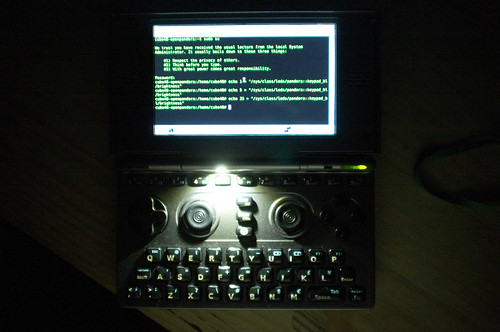
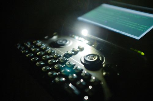
Very short update: I've succeeded and have a Pandora with nice KB light \o/. Going to bed now (2AM). I'll hopefully post a few pictures today evening and start writting documentation this weekend.
 
Last edited by a moderator:
8122878551_53a8749581.jpg


8122881275_057c133ffc.jpg


So, good news, bad news and good news again.


Good one:


All pictures so far can be viewed at my flickr set. I've finished the hack today early in the morning successfully but I already knew that I will have to redo some things. LED was little bit moving in the hole when opening/closing the lid.


Bad one:


In the evening I've opened Pandora again to fixate LED in position. Yesterday I've only stuffed a piece of plastic card behind it, hoping it will hold but it didn't last for long. Also LCD cable was showing signs of wearing out so I planned to replace it anyway. During the lid opening I ripped the LCD cable accidentaly.


Good one again:


I've promptly ordered a new LCD cable and a spare platinum case as some parts were stressed a bit by repeated opening :) Next time I'll stick the LED with Sugru.


And now some more details about the hack.


To mount the cable to the motherboard I made the connector and plug from the multipin connector. I've simply cutted it with boxcutter into two pairs of pins. Bended the legs of one pair to reach the mount pods on MB. The other pair was soldered to the cable so its legs could be plugged into the mounted connector.


In the next step I've soldered the LED to the other end of the cable. That Cree LED is really tiny (and shiny as you'll see in a while :) ). I decided to use white cable for negative pin so I connected it to the catode of LED which is indicated by cutted corner on its front side.


Then I connected the cable and partially assembled the bottom part, leading the cable out through nub button area while the button itself was left out. Booted up, logged in and typed the first magical command into the shell (thanks again, WizardStan ;) ), waiting for the result. And it worked nicely. At that moment I could disassemble the rest of the Pandora and continue with case mod. All went fine as I already knew in detail what exactly must be modified. The only thing that I had to do differently in opose to my plans was the position of the LED. It can't be centered as there is a snap in the middle of the lid case.


The most difficult and time consuming was to put everything back together. Really, I sweated like NHL player as I was concentrating on gentle pushes here and there, trying to not to break anything, aligning all the cables into the right places. Finally I had worst part finished and got to closing the bottom of the case. If I can find some thinier cable, I'll use it next time. The one I used is OK and nicely robust for bending in the hinge but something more subtle could be better for easier placement all the way from LED to the MB.


I did one more boot up and test run without inserting and tightening all screws in case something is wrong. All was fine so I finished the case enclosure. After that I spend some time with testing various light levels.


The conclusion is: it's not an easy hack but totally worth of risk if you are natural born hacker :p For me personally the illuminated keyboard is something that I was dreaming about since I received my Pandora. I spent nearly two weeks with brainstorming, research, planning and preparation (may the force bless ED for his video) which really helped me to keep the total hacking/modding time in under 5 hours (better be slow than sorry). If you ever did the LCD cable replacement, you'll have easier path as the most difficult is the safe dis/assembly of the Pandora. The rest can be done easily with proper tools, steady hand, some soldering skills and common sense.


I'll try to create more detailed instructions, including bill of materials, links and resources, some hints etc.


I'm also considering the insertion of a resistor to avoid the LED overheating. As I wrote in the first post, I have just elementary knowledge in this field so pardon me if I'm wrong in my assumptions. My understanding is that keyboard light pads can provide up to 160 mA so when I send the value of 255 into the file WizardStan mentioned it gives that maximum of mA. After my tests I want to lower the maximum mA to the eqivalent of value 60 (when no resistor is connected) which is app. 36 mA. Ohms law formula gives me 103 ohm resistor (pads provide direct 3.7V from battery). Can somebody confirm please that my calculation is right?
 
Last edited by a moderator:
Pretty cool! In order to determine that resistor, you need the forward voltage of the LED (Vf) from the datasheet. (3.7V - Vf)/(current in amps) = resistor value.
 
PWM doesn't reduce the current, it pulses the voltage. At 100%, it does a solid stream at 160mA (the max possible across the contacts, apparently). At 50%, it flickers between 0v and 3.7v at 160mA. This is why you need an appropriate resistor for full power, because you will be getting full power some of the time and off the other times. The resistor adds load to the circuit and prevents the current from exceeding the LEDs maximum rated amount. If it's a 30mA resistor, that 160mA is probably going to burn it out pretty quickly. Fortunately white LEDs tend to have high voltage drops, so you won't need a huge resistor. This app is what I use for calculating the resistor required. Find out the drop voltage and the maximum amp rating on your LED and plug in to get the correct resistor for a 100% load, and then use different echo values to actually achieve the exact brightness you want.
 
Back
Top