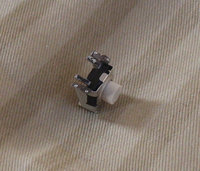
Hardware Damaged shoulder button switch fixture


jA_cOp

Still Fresh
Joined
Jun 4, 2013
Messages
26
Hello,

I've had the 1GHz model from ekianjo for a couple of years and I've been very happy with it.

However, I ran into an issue with the right shoulder button after mapping it to the accelerator in Gran Turismo 2 and probably pressing it too hard for too long at a time. I opened up the case and applied a quick fix with some tape and that worked well for a while, but the problem came back. This time I opened it and noticed that the switch fixture for the right shoulder button had angled quite severely. I applied a bit of force to see if I could gently push it back into a 90 degree position, but alas the switch fixture snapped off the PCB.

PCB and detached switch
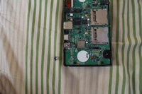
pcb.jpg

Detached switch from different angle
switch.jpg


I'm guessing I'll have to carefully solder the switch back on? Or maybe best to send in somewhere for repair? I noticed that the switch fixture has 4 "legs", two outer and two inner. Are the inner ones for the actual electrical circuit and the outer ones just for support?

Looking forward to repairing my Pandora.

P.S.
I don't have any foam pads of any kind and I don't remember if I ever did. It's possible that I took them out the first time I opened it up and just forgot. Is it also possible that the foam pads were never there in the first place? I don't remember what they look like.
 
Solder it back on and maybe put some hot glue down to support it as it's pretty brittle.

The two inner legs are what you want to get it to work again :)
 
Solder it back on and maybe put some hot glue down to support it as it's pretty brittle.

The two inner legs are what you want to get it to work again :)

Thanks, I've never actually soldered myself before but there's a first time for everything. I've researched it a little bit but I have some questions before I can decide on the exact equipment to prepare.

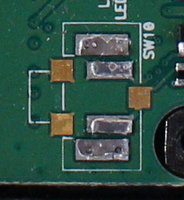
Area around switch
pcb_switcharea.jpg

So the two inner contacts are for the switch, so I have to be extra careful that they don't touch each other (solder bridge), right? Are the two outer contacts merely inert joints for the switch support structure? If so, would it matter if, say, inner leg A is bridged with outer leg A, and inner leg B is bridged with outer leg B, as long as legs A and B don't touch?

What are the three copper squares in the image? I would guess I have to make sure I don't accidentally connect those to anything.

What material are the leg joints made of, and will a typical soldering iron melt it? I'm guessing it won't, so I have to rely entirely on the solder for a good connection?

I'm guessing I should hold the switch in place (maybe with tweezers) and heat the leg from one side and apply solder to the other side. Will the solder flow off to the side or will it be attracted to the joint? Which side should I apply the solder to, considering the stuff around it?

As for the hot glue - I would apply it on top of the two soldered joints after finishing soldering, and probably after testing lightly that the solder works correctly, right? And here it doesn't matter if stuff accidentally touches because hot glue is not conductive, right? Would it be bad if the hot glue touched any of the copper squares?

Finally, will I run into trouble if I try to use lead-free solder for this operation? Probably best to use lead?

I'm obviously not going to do this without preparing carefully, I don't want to harm the PCB, so I highly appreciate any advice!
 
Leaded solder is easier to work with, and cheap soldering irons are unlikely to be able to melt lead free stuff (it melts at about 100 degrees hotter). There is a small issue in using leaded solder; the existing solder on the board should be lead free, due to RoHS legislation, and mixing leaded and unleaded solder can create peculiar alloys which are probably slightly weaker and have a tendency to grow 'tin whiskers' over the course of a few years. But tin whiskers there aren't as much of an issue there than they would be on the legs of a surface mounted chip, for example, and exchanging some slight weakness for the ease of repair is probably a fair trade.

I would try to tin the contacts on the board and on the switch, then you can just hold it in place (with tweezers) and heat each side. Solder will be attracted to the joint once it's liquid, which makes your life somewhat easier.

I guess the switch is made out of steel or aluminium - your soldering iron will not melt either of those materials. I'm not sure what the copper squares do - do they line up with any part of the switch? They may not do anything.

Regarding bridging, bridging on terminal with its adjacent support shouldn't cause a problem, but bridging both would be problematic, as the switch case will conduct from one side to the other. So try not to bridge either side if you can.

The hot glue is not conductive, as you surmise, so as long as it doesn't get into the switch and gum it up or stop you being able to close the case, it doesn't really matter too much where it goes.
 
Leaded solder is easier to work with, and cheap soldering irons are unlikely to be able to melt lead free stuff (it melts at about 100 degrees hotter). There is a small issue in using leaded solder; the existing solder on the board should be lead free, due to RoHS legislation, and mixing leaded and unleaded solder can create peculiar alloys which are probably slightly weaker and have a tendency to grow 'tin whiskers' over the course of a few years. But tin whiskers there aren't as much of an issue there than they would be on the legs of a surface mounted chip, for example, and exchanging some slight weakness for the ease of repair is probably a fair trade.

Leaded it is!

I would try to tin the contacts on the board and on the switch, then you can just hold it in place (with tweezers) and heat each side. Solder will be attracted to the joint once it's liquid, which makes your life somewhat easier.

Ah, good idea, especially since I only have two hands, something I seemed to have forgotten :p

I guess the switch is made out of steel or aluminium - your soldering iron will not melt either of those materials. I'm not sure what the copper squares do - do they line up with any part of the switch? They may not do anything.

For the other shoulder button, which works well, the switch case floats a tiny distance above the midline of the two copper squares which are on the same side of the switch (as the switch case has legs). The third copper square is quite a distance away from everything. Pressing the switch doesn't reveal or extrude anything, I think it just connects internally when pressed. So as far as I can see from this side of the PCB, they don't seem to do anything.

Regarding bridging, bridging on terminal with its adjacent support shouldn't cause a problem, but bridging both would be problematic, as the switch case will conduct from one side to the other. So try not to bridge either side if you can.

Whoops, good point!

The margin between the contact and the support is only 0.4mm (in the image from my previous post, the rectangle made by the white lines is 1cm high), so any spillage towards the margin side will probably be bad. What kind of tip and wire sizes should I be using for this scale?

The hot glue is not conductive, as you surmise, so as long as it doesn't get into the switch and gum it up or stop you being able to close the case, it doesn't really matter too much where it goes.

Thanks a lot for the excellent advice.
 
Yes, those pads do look rather close, but provided you don't use too much solder it should all be wicked to the flat areas covered by the switch contacts, and away from the gap.

One thing I should mention is that while there's no risk of melting the switch housing, that button at least it made out of plastic, and probably a thermoplastic at that, which will melt above a certain temperature. You should only touch the solder iron tip to the surface long enough to heat the case locally and melt the solder, which should only be a second or two at most usually. If the switch top is hot to the touch after soldering you've probably overdone it, and should let it cool before attempting the other side.

Thanks, that makes sense. I'll get what I need, have a go, then get back to this thread with the result.
 
Update on this:

My initial attempt back in May failed; I managed to solder on the switch, but only the circuit and not the two support legs, and it wasn't strong enough. The switch would easily rock back and forth, bending the two inner contact legs.

The other day I brought all the parts including the dislocated switch to an acquaintance with extensive soldering experience, and he fixed it up nicely! First he removed the remaining solder from my botched attempt. Then, he had some sort of paste/solder mixture that kept the switch in place as he heated it up. Neglecting to take the PCB out of the plastic case, the nearby plastic melted and required some filing work to properly accommodate the plastic shoulder button cap, but the end result is functionally good as new, with some minor aesthetic damage :)

Thanks again for all the advice; I just wanted to conclude this properly, and perhaps it could be of use in posterity.
 
Back
Top