[Edit]
We want to improve the design before production, your input is requested.
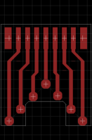
Peca is considering having a PCB manufactured that he is calling TinyBoB, this is to make it easier to solder to the EXT connectors available from WizardStan.
The PCB will be 1.2mm thick or less and may look something like the attached image.
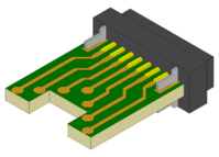
I have made a sketchup file of what it will look like when it is ready to be soldered to the EXT connector you can see a rendering of it attached, I intend to release the file once it is polished with peca's permission (peca I need will pm you with some questions about the PCB dimensions tomorrow).
I have some questions and suggestions:
1. I suspect that it might be a good idea to shorten the traces so they end something like .5-.75mm away from the edge to prevent any problems with solder going from one side of the PCB to the other side. What do you guys think?
2. I have never soldered wires to pads before, I trust it is not to difficult to learn to do?
3. How strong are pad connections compared to through hole connections?
4. It should be possible to modify the PCB design to have holes instead of pads, but would this increase cost?
5. What is the purpose of the cutout in the PCB, would removing this change the cost?
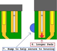
6. I think it might be a good idea to increase the length of the pads that accommodate the metal clips to enhance strength.
7. The pads on the outermost pins go straight to the edge, could this cause problems?
8. Would it be a good idea to have the PCB include physical features to facilitate securing it in some kind of casing, maybe solder pads too?
Thanks so much peca WizardStan and others who are working on EXT port projects. I hope you guys can help me with my media control project.


Last edited by a moderator:


