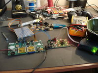
Breakout Board


zevdawg

Member
Joined
Dec 3, 2008
Messages
125
Age
39
Location
Edmonton, Canada
Curious to know, if breakout boards will be released by OP in the future (possibly when?). Wiki mentions something about Gerber files being released as well (possibly) - only manufacturing plants use those (so I thought), so what's that about?

2) Does anyone here know how to read a schematic, and could you build one based off the info in Wiki?

3) The breakout board's needed for realtime debug info isn't it? I would like to become active with helping with all sorts of applications and what have you on the pandora, so a debug log in a console could prove useful to me (for the record I am interested in development, when I get a Panda), but also especially to devs as well

4) what are all the connections on that board?
 
Nah, Gerber files are sufficient for homemade PCB production... there are several viewing/printing applications.

Though you should also know how to read a schematic, in case they don't deliver a component placement diagram.

The layout doesn't look too complicated to me. If you could replace the SMD parts (or use adapters), you could even assemble it on a breadboard without etching a PCB.
 
You don't need a BoB for debugging. You'll be able to SSH in via USB or WiFi. UART access should be generally unnecessary.
 
I want one for hacking OS releases. Nothing beats a serial console for debugging a new boot image.
 
torpor said:
I want one for hacking OS releases. Nothing beats a serial console for debugging a new boot image.

Yes. A jtag cable for example :p

BTW, a seriale console is not strictly needed, we have a screen and a keyboard for the console, after all.
 
Last edited by a moderator:
.. its strictly needed if you want to watch kernel messages on boot while debugging why your keyboard and LCD don't work. D'uh.

And I challenge you to see those messages with a JTAG cable!
 
zevdawg said:
4) what are all the connections on that board?

I did a little digging and I realized that the bread out board is actually breaking out the EXT connector on the back of the pandora. I had just assumed it was connected to an internal header. I guess the ribbon connector threw me but if you check this photo you can see there is a second board that converts the EXT connector to a ribbon connector that then connects to the break out board.

DSC01409.jpg


As far as all the connectors:
J1 - Audio In - 2 x RCA Connectors
J2 - Audio/Video Out - 3 x RCA Connectors
J3 - Serial female DB9 connector - Can be swapped between uart2 or uart 3 via jumpers
J4 - Serial male DB9 connector - Can be swapped between uart2 or uart 3 via jumpers
J5 - Can't tell for sure but mostly likely a mini-din connector for s-video.
J6 - 5x2 connector - Breaks out the alt functions allowing for GPIO on some pins.
 

Attachments

  • DSC01409.jpg
    DSC01409.jpg
    387.5 KB · Views: 144
Last edited by a moderator:
torpor said:
.. its strictly needed if you want to watch kernel messages on boot while debugging why your keyboard and LCD don't work. D'uh.

And I challenge you to see those messages with a JTAG cable!

And what if the serial is not working? :p
 
Last edited by a moderator:
Then I'd use JTAG! :) Which is of course also on the Breakout board. But at that point I'd just get another Pandora, because it'd obviously be a hardware problem, and I'm not getting a Breakout board to debug hardware problems, but to debug new OS boot images ..

Anyway, pedantish cur, begone!
 
Back
Top