Battery power supply for SBC and screen


kuru

Laptop und Trachtenjanker
Joined
Oct 8, 2008
Messages
3,367
Location
the mockracy
I want to run a single board computer - likely an Orange Pi 5 - and a screen on batteries. The board needs 5 V, the screen 12 V. I've read around a bit, and apparently using two voltage regulators for each item should do the trick. Which is baffling to me since reading about voltage dividers. Will that work without magic smoke?

Should I go with one big cell, or a number of small cells in parallel, and step-up regulators? Or four cells in series, and step-down regulators? I could use cylindrical cells with a protection circuit, and charge them in a dedicated charger. Which I'm not a fan of: inconvenient, big and heavy. Would rather use pouch cells. Which are also available with protection, but can't easily be charged externally.

Disregarding the options above - if possible I'd like to have the additional convenience of plugging in and charging this monstrosity during usage, just like a phone or laptop. Will a/any BMS do that?

What's important: Not killing myself in a fiery disaster and readily available parts.

These things are nebulous to me, and the options are plentiful - thank you in advance for your input!

Edit: I found this UPS for raspberry pi https://wiki.geekworm.com/X728#Overview
Claims up to 6 Amps, that should sort out the Pi 5. The pins wouldn't line up though, so that's a hassle. And I'd want to remove the battery holders because of their size, and replace them with a connector for a pouch cell. I'd likely make a mess there, the holder looks surface mounted.

Edit: I learned that pouch cells usually are li-po as opposed to NMC cylindrical cells and are not interchangeable.
 
Last edited:
ok, slow down a bit. what batteries do you have access to? this will determine the solution for you.
linear regulators are not a good idea as they are not efficient and waste power via heat. This means a resistor voltage divider like you first said or the traditional 7805 voltage regulators.

the ideal would be at least 2 18650 cells giving 7.2V nominal 8.4 fully charged. then using some cheap ebay buck converters to get 5V at 3A for the orange Pi and a boost converter to get your 12V for the screen .
I have seen LCD screens rated at 12V work quite well on a lower voltage so the option to use 3 18650 cells for a 12.6V full charge and usable down to around 10V would power the screen directly and then just the 5V buck converter for the 5V to run the Pi . depending on the cells 2000mA capacity is about average. Reclaimed laptop batteries are usually 2000mA. a simple $2 3 cell BMS will protect the cells and charging of them. if 2000mA are not enough of a run time the simply parallel them so 6 cells in a 3S2P config will work fine and the same BMS is ok for both. The number of batteries will be determined by how long you want this system to run. the Pi will take more power than the screen . so the 3s2p battery would last about an hour to hourand a half depending on how hard the pi is running.

I build 18650 cell battery packs all the time. Built one a week ago with a variable put put on the converter to give me 8V to drive my Canon camera from a large pattery pack for Astrophotography.
 
Just saying: Usb-C is multi voltage.
So a powerbank with usb-c port is all what is needed. You can just grab a 12V usb cable if you dont want to wire the pins yourself.
Or if you insist on building your own battery, this is at least where you can source reliable parts from.
 
I would say something like elw3 stated. Try to use off-the-shelve components if that's an option. If you didn't buy any hardware yet, you probably can get an SBC + screen both using USB-C and use a regular powerbank for power.
If you use a 5V lipo you probably can use the 5V directly (still regulated) and a boost converter for the 12V.

It might also be implied you want it to work in a mobile setting, not a fixed location but having a back-up battery (like a UPS). So you have some requirements for mobility, like weight, size and ease of use.
If not, it will be a lot easier. I assume this setup is too big for you: https://hackaday.com/2020/10/19/simplifying-the-ruggedized-raspberry-pi-portable/
 
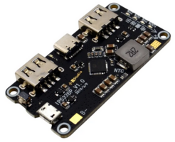
1) e.g. IP5328P module
IP5328P.png

1A) with a bunch of 18650 in parallel. Maybe even use battery holders.
Could the cells be arranged like this?
rundzellen-parallel-längs.jpg

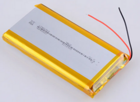
1B) or simply a single lipo (It's crazy how cheap those are when you buy ten, only ~7€ a piece at 10Ah)
Screenshot 2023-10-03 at 16-11-21 8.37€ 36_ OFF Power Bank 10000mah 3.7v Batteries - High 3.7v...png


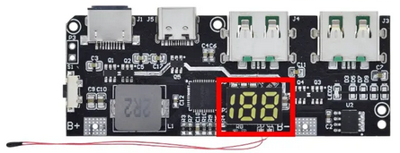
2) or this more expensive module that allows serial connection. The solder points for B1, B2, B3 are on the back.
Screenshot 2023-10-03 at 16-36-57 2.68€ 12_ OFF Qc4.0 Qc3.0 Led Dual Usb 5v 4.5a 22.5w Micro_t...png
I assume that would be easier on the cells because of less amps drawn. And more efficient in conversion as said in an above post.
This has a convenient percentage display. But in order for that to be accurate I'd have to replace a tiny resistor. It comes preset to 10Ah cells.

Apart from all the above - would you use cells with individual protection boards, or would those interfere with the regulation of the boards?

Is there some sort of splitter that takes one USB-C in and can put two USB-C PD with independent voltages out? Edit: apparently not, only wall warts will negotiate different output voltages.

Edit 2023-10-08 04:04
Seamuing Raspberry Pi 4 UPS Hat looks interesting

Edit 2023-10-08 20:31
I've ordered an OPi 5+ and the UPS. Paid a premium for the SBC from a .de-seller on Amazon. I feel safer compared to ordering expensive stuff from Chinese resellers over Ali.
I also ordered a Waveshare 11.6" IPS display unit. Would have loved to have an OLED screen, but those are only availble at either 5.5" or 15.6" when it comes to 1080p. There's higher-res screens availble, but those will consume more power.
First test will be if the UPS can power both the screen and SBC without problems. If that does not work, a custom solution is required.
 
Last edited:
Yes you can parrallel the cells like that even the pouch cells , you may still want a BMS to avoid poorly charging the cells. That more expensive board is to add the batteries in series for 11.1V.

That panel requires a 12V 1A Power Supply. the orange pi 5+ uses a 5V 4A power supply.
thats 32W combined. i cant find any info on the UPS on the orange pi website. as i said in my first reply, you are going to need 2 power boards to run from the batteries. a boost converter to use 3.7V to 12v at 1A and a second to do the 5V at 4A from 3.7V Li ion 18650 cells or pouch cells. 32W/3.7V is around 8.6 A from the batteries of course thats at max power draw when cpu loaded add a bit more due to inefficiences in conversion on both boards call it a round 10A . Thats 10AHr required for each hour of operation , the number of pouch cells or 18650's will depend on how many hours you need this to run from batteries.
 
Just saying: Usb-C is multi voltage.
So a powerbank with usb-c port is all what is needed. You can just grab a 12V usb cable if you dont want to wire the pins yourself.
Or if you insist on building your own battery, this is at least where you can source reliable parts from.
The trouble is that most powerbanks use the usb-c to recharge themselves or only have 5V 3A on usb-c. one that i saw had power delivery didnt offer 12V only 5,9,15...
 
Let's say I don't care about charging during use. Add a single USB-C input with 12V trigger board. Then directly connect the screen, and in parallel a buck converter for the SBC. That would easily run off a wall wart, or one of the beefier power banks.
Code:
https://www.amazon.de/dp/B0BZCPQJFM/
This one even has dual USB-C out. It's quite a slab though. Maybe put something similar in a keyboard base... hm!
Finding an efficient and not too large buck converter seemingly is not that easy. I've looked at quite a few tests of China modules, and most only do about half of their advertised amps.
 
OPi 5 Plus with nvme, wifi/bt stick and thinkpad compact keyboard running off https://github.com/rcdrones/UPSPACK_V3/blob/master/README_en.md goes on for almost five hours on idle, using roughly 5 Watts.
UPS-Pack is being a bit weird though. It has four LEDs to indicate charge. The last one is supposed to start blinking at 3,45 V. 2,5 hrs of the runtime were spent with the blinking LED. It shut off completely close to 2,5 hrs later. The lipo then sat at 3,37 V. Should have checked if the voltages for the other indicated levels match. Maybe the discharge curve is just that flat? Anyway, thinking about adding another lipo in parallel.

RK3588 has a PMU power management unit for toggling groups of processors etc., but so far I haven't found out how to use that. I'd like to e.g. shut down the NPU which I don't have use for. Or deactivate the big cores when I'm only streaming video via web or local sunshine/moonlight.
 
Last edited:
RK3588 has a PMU power management unit for toggling groups of processors etc., but so far I haven't found out how to use that. I'd like to e.g. shut down the NPU which I don't have use for. Or deactivate the big cores when I'm only streaming video via web or local sunshine/moonlight.
You should look into the dts what thermal options there are, and maybe modfify, recompile to dtb and install them. Then play with /sys/class/thermal/*
Maybe have a look at
Documentation/devicetree/bindings/thermal/thermal-cooling-devices.yaml
Documentation/devicetree/bindings/thermal/rockchip-thermal.yaml
Documentation/devicetree/bindings/cpufreq/cpufreq-dt.txt
Documentation/admin-guide/pm/cpufreq.rst
Documentation/power/energy-model.rst
 
Next to the UPSPack V3 there's the Geekworm X-UPS. Another pretty neat project UPS. It can do 5 V and 12 V.
ups.png

website blurb
Battery Charging

Supports 3000mA fast battery charging

Battery over current protection and over voltage protection

Protection of battery cell Reverse Connection

Lowbattery detection (LED and 3.3V level output)

Onboard 4 green LEDs indicate battery charging and discharging levels of 25%, 50% , 75% and 100%

18650 4cell lithium Ion holders

Power Input

Integrated highefficiency stepdown DC/DC converter

Wide 6V to 24V operating input range

Up to 95% Efficiency

Up to 10A output current to keep 3A fast charging and powering your SBC at the same time

Allows powering from a car, a solder pannel and other power sources

Most common power input jack: 5.5x2.1mm

Power Control

Onboard push button to control power on /off (PressON, Hold the button pressed at least 3s OFF )

Onboard LEDs shows the status of power output

AC power loss or power adapter failure detection (LED and 3.3V level output)

Jumper setting to enable Auto power on when power applied or restored

Jumper setting to disable 12V output

Ultralow standby power consumption to maximize battery life

Advanced system powerpath management avoids batteries frequent charging and discharging

Misc

Power output connectors : VH3.96 x2 (12V) / XH2.54 x2 (5V) / USB TypeA x2 (5V)

PH2.0-4P for external power switch

PH2.0-4P for low battery and AC power loss deteciton

[Specification]

Power input (Single board) : 6-24Vdc ±5%, ≥3A

UPS output voltage : 12Vdc ±5%, 5.1Vdc ±5%

UPS output current (Single boards) : Max 3A

UPS output current (Stackable boards) : 3A x No. of the boards

UPS charging current (Single board) : 2.3~3.2A

Terminal Battery Voltage : 4.24V

Battery Recharge Threshold : 4.1V

Battery low detection: ≤3V
 
Back
Top