Displayboard: Difference between revisions
Jump to navigation
Jump to search
(Added picture, mentioned rotator chip) |
No edit summary |
||
| Line 1: | Line 1: | ||
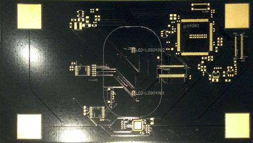
[[File:Display pcb unpopulated prototype.jpeg|500px]] | [[File:Display pcb unpopulated prototype.jpeg|500px]] | ||
*The PCB that is behind the screen, connected between the [[Display]] and the [[Mainboard]] | *The PCB that is behind the screen, connected between the [[Display]] and the [[Mainboard]] | ||
*Carries the [[Display#Rotator| Image Rotator Chip]] | *<strike>Carries the [[Display#Rotator| Image Rotator Chip]]</strike> | ||
*Carries the Touchscreen Controller | |||
*Also carries two RGB LEDs that shine through the logo on the back of the lid. See: [[LEDs]] | *Also carries two RGB LEDs that shine through the logo on the back of the lid. See: [[LEDs]] | ||
Revision as of 18:39, 14 April 2017
- The PCB that is behind the screen, connected between the Display and the Mainboard
Carries the Image Rotator Chip- Carries the Touchscreen Controller
- Also carries two RGB LEDs that shine through the logo on the back of the lid. See: LEDs
